End Of Life
EOL also mean: NO SUPPORT
You make it at your own risk.CHARACTERISTICS.
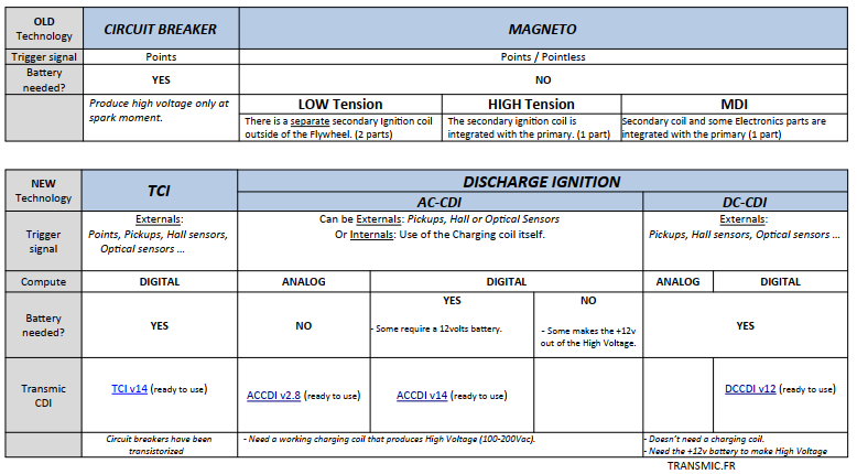
- DC-CDI
- Easier start when cold
- For SINGLE cylinder (and SOME TWO cylinders).
- Advance curve is in EEPROM and is freely modifiable
- Rev until 20,000 RPM/330Hz
- Pickup position can be freely set from 0 to 360°
- Accurate (0.15°/8000RPM).
- Need a 6 or 12 volts battery
- Current drain: 2mA to 1.5A
- Power: 40mj
- No need of HV source coil on the stator
- Autotest jumper
- Kill switch connection
- Dimensions: 91 x 58 x 28mm – 67g
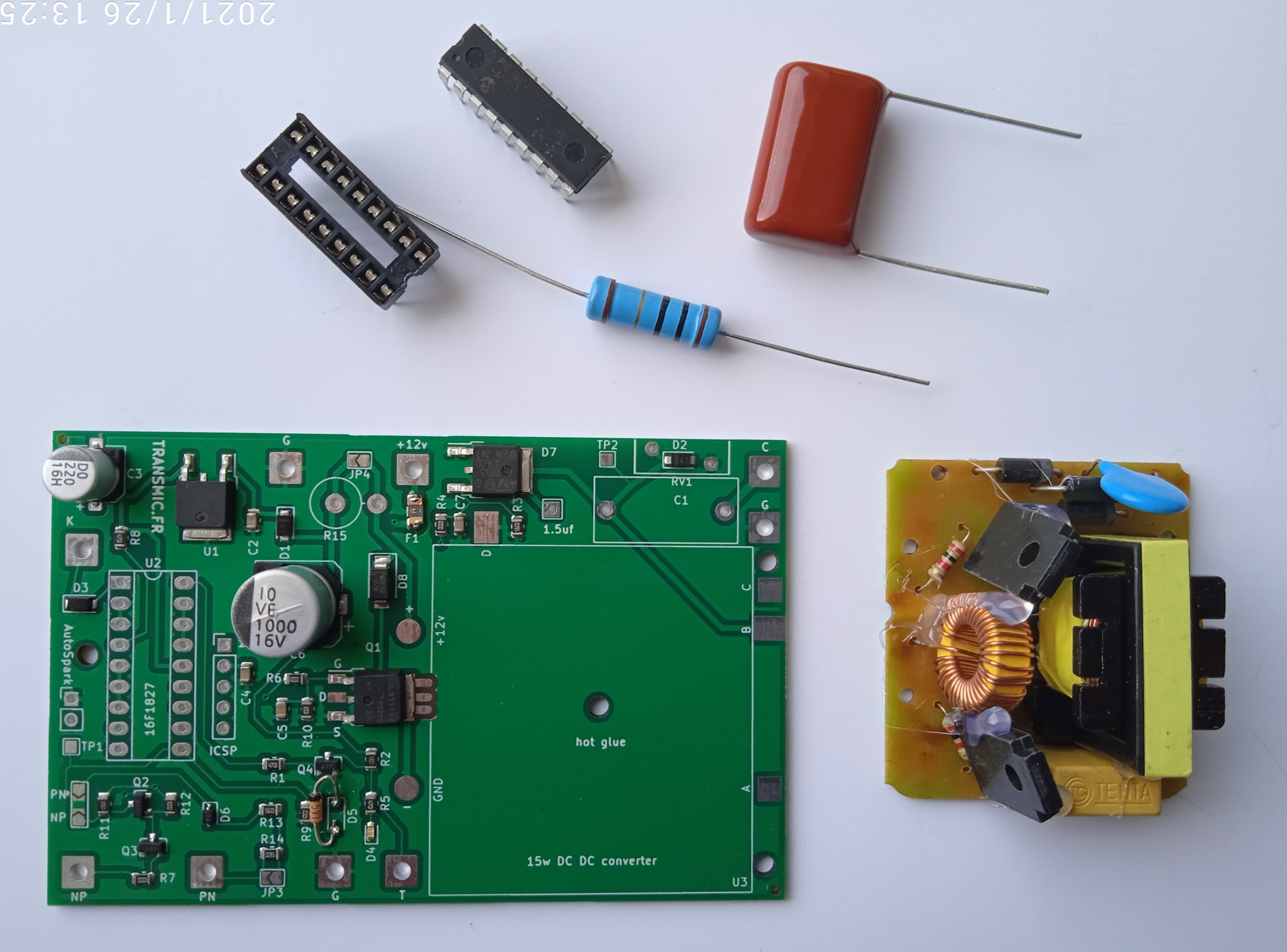
WHAT DO YOU NEED?
| PCB, DC-DC Converter, Electronic components and Programmed 16F1827 PIC microprocessor (Source code is not available.) |
Everything | |
| Schematic | Hardware Version V7R7C9 | |
| Components view | Placement | |
| Create the ignition timing curve | Excel file v79r25c1 | |
| To program your own advance timing map. | PICKIT3 software | |
| To burn the 16F1827 | PICKIT3 programmer | |
| Wiring | Connect the DCCDI to the bike | |
HOW DOES IT WORK?
At idle and low RPM, the PIC generates maximum delay before fire a spark a few degrees ahead of TDC. That way, there is no or little advance at low RPM.
As the RPM increases, the more the advance would increase ahead of TDC accordingly.
The PIC follows your ignition map programmed in EEPROM.
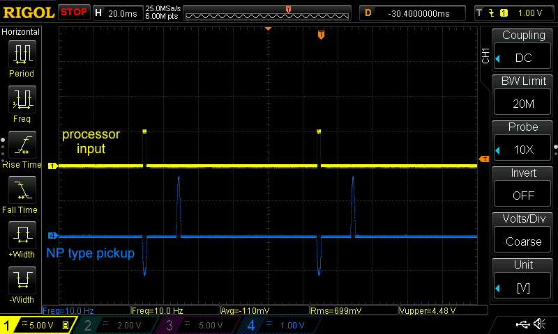
Pickup signal must be > 2 volts in order to be detected by the PIC
A pulse is available at pin 1 and trigger the SCR.
The pulse length is adjustable from 500us until 5ms or can be automatically adjusted.
DC-DC Converter
The microprocessor drives a on-board 15 Watts DC-DC converter to raise the 12Vdc from the battery to 200Vdc.
– Better startup when engine is cold.
– A DC-CDI can be a substitute to a faulty stator (charging coil).
– When no pickup signal is detected, DC converter stops and goes in sleep mode. (2mA)
– Power selectable:
– 40 millijoules (40 mJ) with R7.
Transistors need heatsinks if this unit run at 10.000rpm longer then 1 minute.
– 50 millijoules (50 mJ) without R7 resistor. (video) Always add heatsinks!
– HowTo wire the DC converter to the PCB?
– Some measurements done on scope.
PICKUP
– 1 input for inductive pickup with 1 signal per crank rev.
– Pickup must puts out 3 to 30Vac
– Points, reluctors, Hall sensor, optical sensors can be used as long as they give only 1 pulse per revolution.
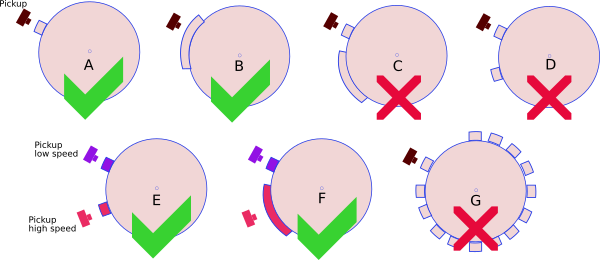
– This CDI works with 1 pickup and 1 reluctor (the metal strip on the flywheel) [A,B].
– This CDI works with 2 pickup and 2 bars [E,F].
– This CDI DOES NOT work with 1 pickup and multi-pulses pickup (ie 2 reluctors on flywheel) [C,D].
– This CDI DOES NOT work with 1 pickup and missing tooth flywheel [G].
How to calculate the Pickup Position?
- Find the TDC
- Read comment here and here
Pickup wiring.
Click here for more info...Variable Reluctance coil (VR)
PIC processor ONLY detect the positive going edge of the trigger pulse.
That mean the FIRST pickup pulse coming to the processor MUST be Positive!
– If this is the case (like Yamaha, Kawasaki most often) connect the pickup to J10 input and close JP2 solder pad in PN position.


– If your pickup gives out a NEGATIVE first pulse, (like Honda, Suzuki, Zongshen, KTM most often), the timing will be bad…
There are 2 solutions:
1) Just invert the 2 wires that come from the pickup to the CDI if none of them are internally connected to GND!
or
2) connect the pickup to J9 input and close JP2 solder pad in NP position.
(This way Q2, Q3 transistors will reverse the first Negative signal so it becomes Positive.)

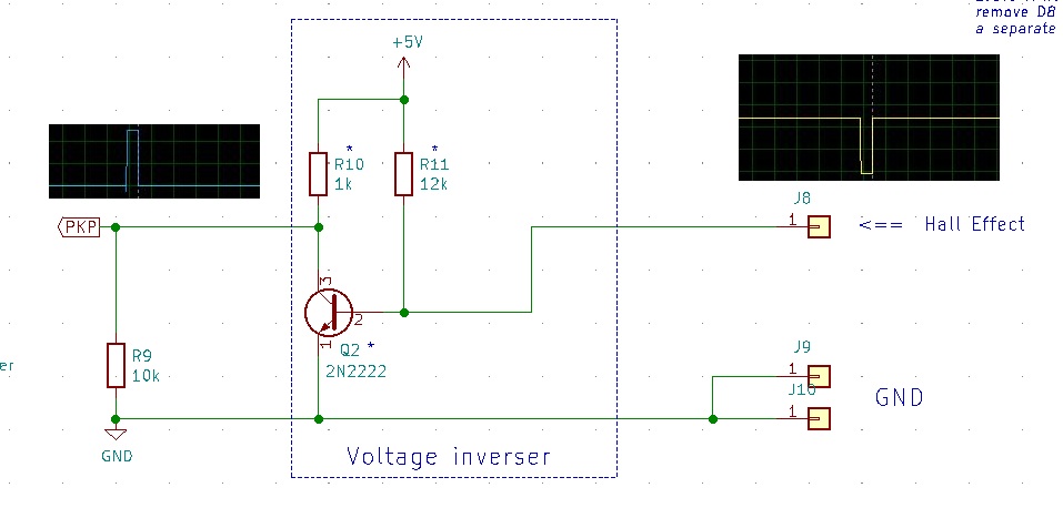
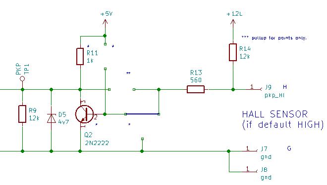
HALL EFFECT SENSOR
Most often, Hall sensor output are default HIGH, going LOW when a magnet pass in front of them.
To use an Hall sensor with ACCDIv79 or DCCDIv79 you need to invert the signal with one NPN transistor then connect to JP10 (JP2 solder pad in PN position.)
CDI Programming
The PIC that comes in the KIT embeded a protected software, but the EEPROM zone is Read/Write allowing you to write your own ignition timing into the internal data EEPROM.
You can change the advance timing by yourself as often as you want!
The PIC comes with an empty Eeprom. Before to use it, just draw the new curve in the excel sheet, write datas in the PIC’s EEPROM using a programmer then restart the CDI.
That’s all done!
Draw the advance curve
Click here for more info...
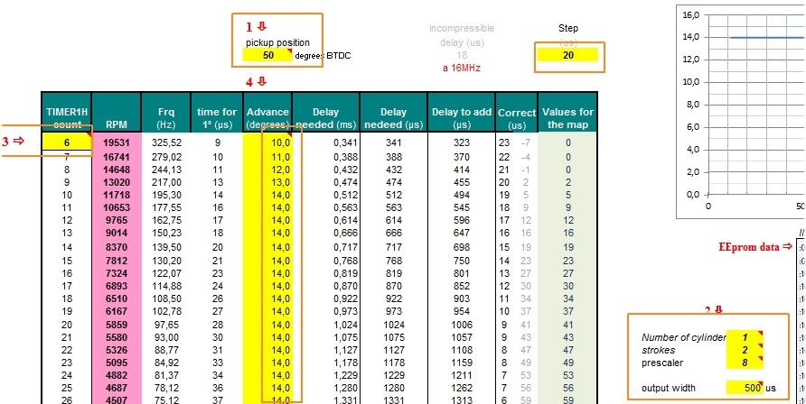
- Use the Excel sheet (in download section above) to define the timing curve for your bike:
-
- Only change the yellow cells.
- Enter the pickup position (which is slightly more than the max timing advance your bike uses) in cell F5.
- Select the number or cylinders (cell O24) and the number of strokes (cell O25)
(select 2 if the engine is a 4 strokes with wasted spark)
The pulse coming from the PIC that trigger the SCR can be adjusted from 500us until 5ms or in “AUTO” mode (cell O28).
Except for specials needs or lazy SCR, leave the default value of 0.5ms. - Select the maximum RPM by changing the variable TIMER1 in cell B9.
- Play with prescaler value in cell O26 AND with TIMER1 value (cell B9) until the excel sheet displays the whole RPM range you want and the advance values don’t strike “Out of range” errors.
- To manipulate the points of the curve, type in the advance you want for each RPM in column F.
If you run into “Out of range” Warning messages column M, try to:
- Change the advance values column F
- Change the RPM range cell B9
- Use another prescaler value cell O26
- Use another step value in cell L5
Play with those steps above until the curve fit in the excel sheet.
Any Excel Errors will result in a faulty HEX file that will not work !
Warning are not critical, but you won’t get the exact timing you want.
Excel Error are critical.
When done:
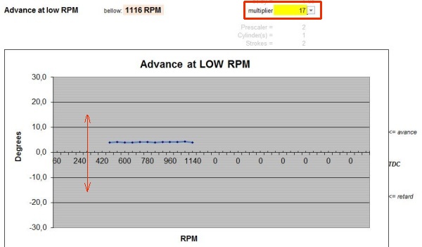
- Adjust the advance for low RPM with the help of the multiplier value in cell I2 of the Excel tab named “advance_at_lowRPM“.
If the maximum RPM become too low, raise it with cell B9 and so on…
Play with prescaler value (cell O26) and multiplier value (cell I2) to change the low RPM range.
PROGRAM YOUR IGNITION MAP
Click here for more info...
The PIC that comes with the KIT embeded a protected software, but the EEPROM zone is empty.
Having no data the processor cannot produce sparks!
You must first fill out the Eeprom zone with the timing you want.
Load the Eeprom file with PicKit3 (IC-Prog or PICkit2 don’t support this PIC.)
Don’t forget to UNCHECK “Program Memory” to avoid wiping out the Firmware!
Don’t press the ‘Erase‘ button, this will also wipe out the firmware memory even if ‘Program Memory‘ is unchecked!
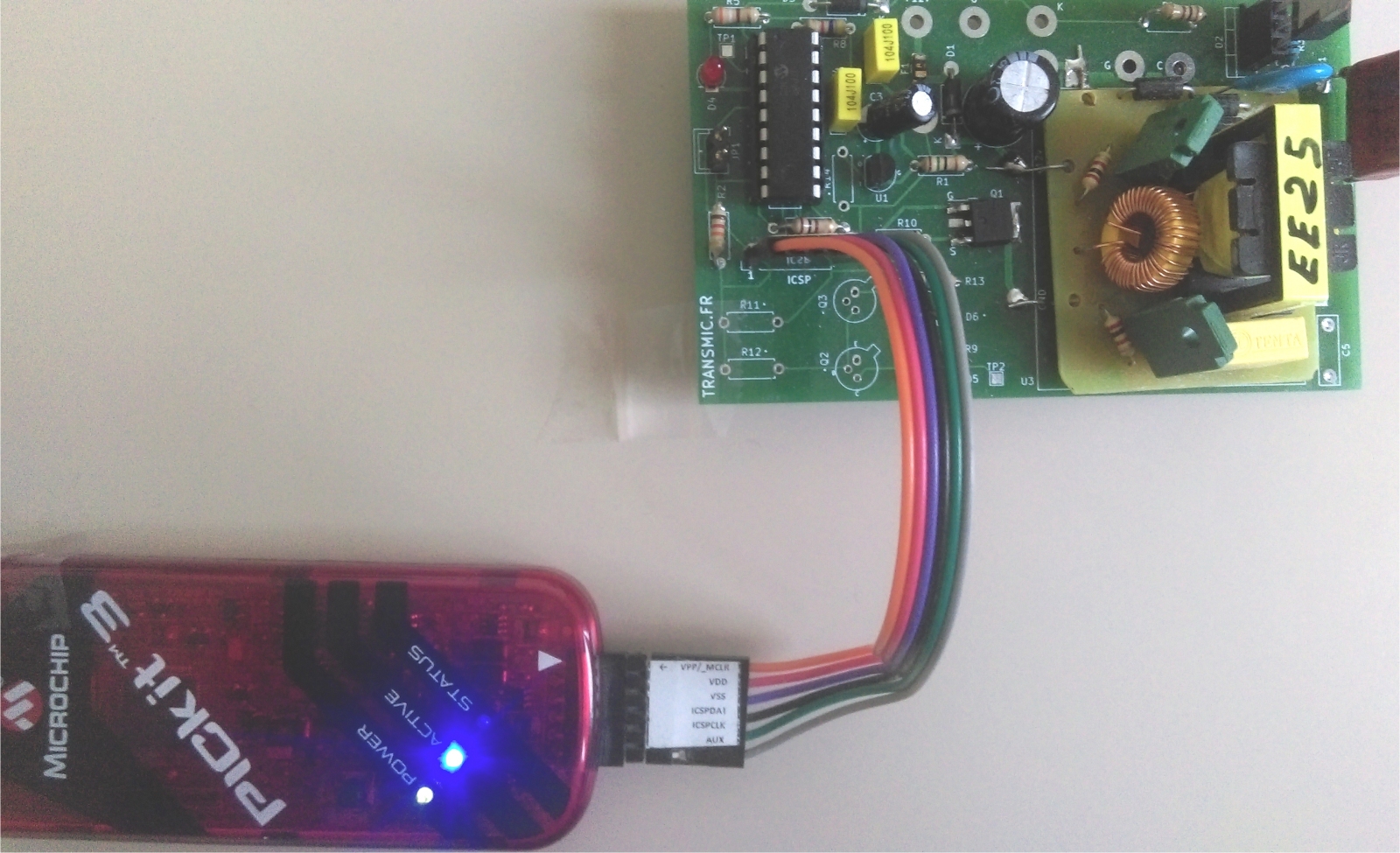
- Use a serial/USB programmer then insert the PIC into its socket on the DC-CDI board:
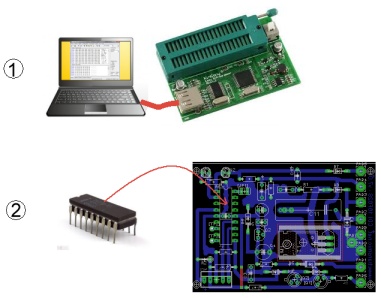
- or use the ICSP connector to program the PIC 16F1827 in situ with PicKit.
- See video of the burning process.
(This video had been done with a 16F1847. For a 16F1827 just select the right PIC but the process remain the same.)
 (More info on ICSP in comment section)
The process is also described here: CDI programming with PicKit3 Software
Once done, I suggest you to test the DC-CDI with the “Autospark” feature (JP1 jumper close).
The processor will send sparks independently of the advance timing. This way you can test the hardware first !
Some guys seem to run into issue with Pickit3, here are some info that could help you to Troubleshoot Pickit3
Accuracy
- Error in degree:
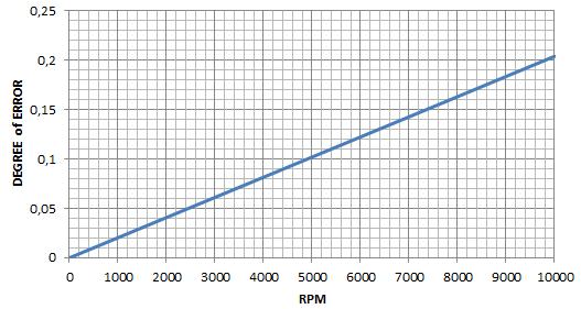
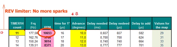
RPM limitation:
Above the last RPM value on top of the XLS sheet, there are no more sparks.
Below: If RPM goes over 10653, sparks stops.
DIAGNOSE with LED
Click here for more info...– At startup, Led D4 flashes 1 to 4 times and goes off meaning that PIC .HEX software is OK.
If it doesn’t flash, something went wrong with the programming or is wrong with the power line…
– 1 time = PIC has been reset because power went below +5v.
– 2 times = PIC has been reset because +5v power went off.
– 4 times = PIC has been reset because of the RESET pin4.
– blink forever = Eeprom is empty
– When PIC input pin10 is high [>2.4v], led D4 (pin18) is on. So D4 LED pulse with the pickup.
If D4 LED always stays ON, that mean either:
– pin10 is always high! => Measure pin10 and try to lower R9 to 1.8Kohm or less according to the pickup…
– or CDI is in “Autospark” mode.
Jumpers
Click here for more info...JP1: AUTO SPARK
– Hook a ignition coil to the DC-CDI, with its sparkplug connected to a solid ground.
– Put a jumper ON so RB2/pin8 is connected to ground.
– Power on the DC-CDI
– LED blinks 3 or 4 times and stay steady ON when the PIC self generate sparks at 3000RPM without the need of any pickup.
See Video
Please note that:
- Soldering R2 is mandatory!
- JP1 is tested once at boot time! So if you move the jumper, reboot the CDI.
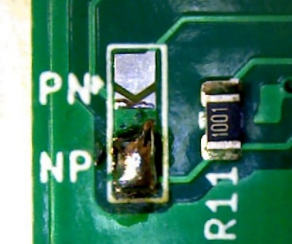
JP2: PICKUP TYPE
– If the pickup gives a Positive first pulse, then connect it to PN input and close JP2 in PN position.
– If the pickup gives a Negative first pulse, then connect it to NP input and close JP2 in NP position.
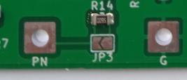
JP3: PICKUP SENSITIVITY
– open (default) : Low sensitivity. For pickup that gives 6 to 50Vac.
– close: High sensitivity. For pickup that gives 5 to 20Vac.
Troubleshooting
Click here for more info...Reset diagnostic
After a reset:
– If led blinks 3 times it means that +5v has been cut (CDI has been powered off.)
– If led blinks 4 times it means that a RESET occurred (Manual or due to parasitic transient/aka EMI)
EMI
Electromagnetic Interference comes when external high dV/dT append nearby the processor.
– Only use ignition coil designed for CDI (not for TCI!)
– Use 5K to 20Kohm spark cap noise eliminator
– Use shielded sparkplug wire
– Ground shift: Sparks induce high current in the ground line. If gnd trace or wire are too narrow, ground level will raise up. Use a separate strong ground wire as close as SCR’s cathode as possible. Don’t use a unique ground path for microcontroller AND ignition coil!
– Add a filter across the SCR (snubber, varistor, Ferrite bead choke)
– Search for bad solder joint
– Use a good power rail strong and stable, can need more caps on it. (100uf + 100nf + 10nf)
– Add 100nF decoupling cap to power supply pins as close to the PIC as possible
– Add 100nF between reset pin (MCLR pin4) to ground
– Lower R1 pullup resistor to 4.7k
– No floating pins. Ground any unused pins if they are at low state.
– Use the last firmware
– Shield the circuit: Enclose the PCB inside a metallic box connected to ground.
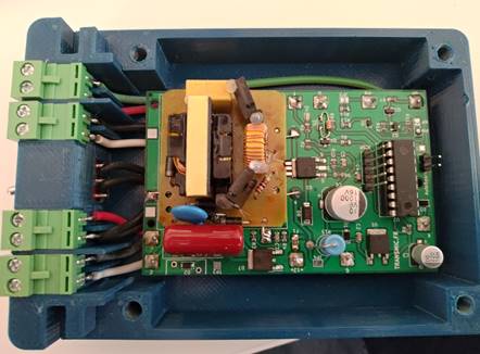
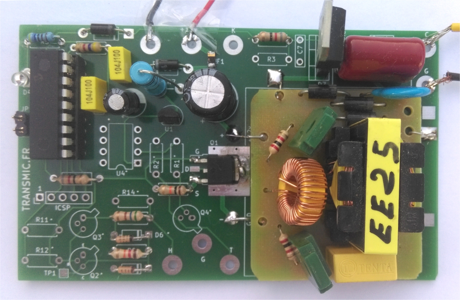
PHOTOS.
Click here for more info...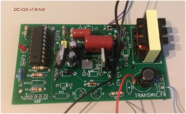


VIDEOS.
Click here for more videos...How a pickup works?
Honda CY80 converted from Magneto to DCCDI running until his pickup breaks!
On the bench, measuring DC converter transistors at 52°C
VERSIONS
Click here for more info...- Version 7.9R17r1c0:
- [hard.] PIC 16F628 at 4MHz.
- [hard.] Prototype with a hand crafted transformer.
- Version v7r2c0:
- [hard.] PIC 16F1847 at 16MHz.
- [hard.] Prototype with a complete DC converter.
- [soft.] Bug corrected under 500rpm.
- Version v7r3c1:
- [soft.] Major improvement at low RPM (Works from 42RPM).
- Version v7r4c0:
- [soft.] Alow pickup position from 0 to 360°.
- [soft.] Bug fix when 100us steps
- Version v7r5c0:
- [hard.] PIC 16F1827 at 16MHz.
- [soft.] Power of DC converter: 20mj.
- Version v7r6c0:
- [soft.] Sleep mode if no pickup detected. (only 2mA)
- [soft.] Power of DC converter: 50mj.
- Version v7r7c0:
- [soft.] Accuracy increased
- Version v7r7c1-c2:
- [soft.] Bug fix at 450rpm
- [soft.] Improvements
- Version v7r7c3-c4:
- [soft.] Bug fix between 470-1000rpm
- Version v7r7c5:
- [soft.] Change HV generation
- Version v7r7c6:
- [soft.] Fix HV generation
- Version v7r7c7:
- [hard.] Add D8, change R13
- Version v7r7c8:
- [soft.] Free version increased to 50 trials
- [soft.] improvement to avoid false detection of pickup pulses
- [soft.] improvement to deal with slow rising/falling pickup signal at low RPM
- Version v7r7c9:
- [soft.] Bug fix
- [soft.] Add a reset diagnostic
- Version v7r7c10:
- [soft.] Error fix at low RPM
- Version v7r7c11:
- [soft.] Error fix in Autospark function
- Version v7r7c12:
- [soft.] Add a debug function
- Works on v7r7c8 hardware with SMD parts.
- Version 7R8c0:
- [soft.] Major correction of advance timing at low RPM to ease kick start
- [soft.] Now 160 RPM values are adjustable (+66%)
- [soft.] Lowest RPM is now 100 RPM
- [soft.] Use different step value for low and high RPM to avoid too many XLS warnings
- [soft.] LED blinking at startup can be disable to speed up the start
- [soft.] First measurement of RPM can be disable to speed up the start
- [soft.] Add an optional hysteresis to filter noisy VR pickup
- [soft.] Add Debug diagnosis with LED
- [soft.] Better detection of slow pickup signal
- [soft.] Better protection against EMI
- [soft.] Correction: RPM now changes when 4stk is selected
- Version v7r9c1:
- [soft.] Better accuracy at 400rpm
- [hard.] Add a 1.5A Polyswitch fuse.
- [hard.] New v7r7c9 hardware with SMD parts.
- Version v7r9c2:
- [soft.] Correction of a faulty Tacho output
- Works on v7r7c9 hardware with SMD parts.
- Version v7r9c3:
- [soft.] Led blinks if is eprom is empty.
looking forward to getting my hands on it, please let us know when its available
Thanks for your interest.
Actually I had some problems with the prototype… It worked but wasn’t reliable enough (EMI, Heat…) that destroyed a few PICs and Mosfets over the time!
Now I’m using another converter and the results are good and stable.
10 firsts PCB have been ordered and I expect them to be here end of October to release a first shot of 10 Kits.
Hi Thierry,
Transformer in the photo can be purchased or has to custom build?
tq.
Hi,
No need to build one, it will be part of the KIT.
Th
Hi thierry,
“…Oct the 30th. Hitch! The oversized DC converter destroys SCR… I have to change the schematic and order new PCB That slow down the release to December!”
You are living an unpleasant situation.
Hang in there, you will find the solution.
Best regards.
Sylvain.
Hi Sylvain,
I finally found a software workaround to calm down the DC converter!
It’s also possible to add a 10ohm 0.5w resistor in series with D1.
That reduce the max rev to 13000RPM too.
Necesito un tci para una moto suzuki gsx 400 fws es 4 tiempos 4 cilindros con 2 captores y 2 bobinas dobles ocea con chispa desperdiciada 1_4 y 2_3 tira al mismo tiempo se puede hacer con un pic o necesito dos? Gracias saludos , abrazo desde Argentina..
Please use ENGLISH ONLY.
When everything is double (1 pickup+1 coil for 2 cyl) you could use 2 separate TCI.
But TCI IS NOT CDI
software and hardware are different.
Hi Thierry,
I have two questions:
First, concernig my programming device.
Is it still compatible with winpic800 ? I dont see this pic in supported device…
Second, concerning my hall sensor pickup.
when no magnetic field detected, the output is high and low when detected, the signal is inverted with classical pickup.
Should I provide a signal inverter (transistor) or not necessery it will work well.
Regards,
Sylvain.
Thierry,
The answer at my question2 seems to be evident.
If I refer the schematic, I will have to install neither the transitor Q3 nor the diode D6 and link the Q3 emitter pin hole with Q3 collector pin hole.
Do you agree with that ?
Sylvain.
Hi Sylvain,
No I disagree. You must use this schematic for this specific use case:
https://transmic.net/wp-content/uploads/2019/11/input_hall2.jpg
Re winpic800, I don’t know this soft. I can certainly move the software into a 16F1827 which is more widely known….
Let me a month to do that.
Thank you Thierry, 16f1827 is supported.
About my hall sensor, I need to pullup the output, either with 5v or 12v.
For this reason, I use R12 and remove R14 for 5v pullup.
Although, I would have preferred pullup 12V in order to avoid an hypothetic 78L05 regulator overload…
Then the schematic you can use is:
Many thanks Thierry,
Let me know when your 16f1827 update will be available, if not I will invest in PicKit3.10 and purchase the kit shortly
Hello Thierry,
I am considering updating the electrics on my 1975 single cylinder 4 stroke Gilera using Chinese GY6 generator parts and your DC-CDI unit.
Due to limited space in the engine casing it will be necessary to position the pick up sensor a long time BTDC, possibly as much as 250 degrees BTDC. Will your software/firmware cope with that situation?
Hi,
Download the XLS file above and try a 250 value for “pickup position”, even with a 100us step it will not work below 1500RPM
(in one word it’s way too long for the PIC’s 8bits counter to wait from the pickup time to the spark)
Unless I mod the code to add another step of 200us, that seem feasible if it doesn’t trigger other issues….
Hi Thierry,
Thank you for your speedy reply.
Feel free to disagree but my experience suggests to me it is best not to get into modifying working code, as you say, it may well introduce issues that could prove difficult for me to diagnose . . . is the gremlin hardware, software, mechanical.
I think it best I concentrate on re – engineering the trigger positioning to better suit your working code.
I was hoping to get away with not removing the rivets that secure the magnet housing to the crank mounting hub. Along with the need to rebalance, when in use, there is substantial torsional vibration present at that joint that rivets are particularly good at accommodating. I don’t fancy re – riveting, likely to wreck the magnets, magnets do not like shock treatment. Maybe I can turn up some sleeve bolts….I’ll have a think about it.
I’m getting old, it’s currently too cold for my old bones to tinker in the garage anyway.
I will buy and build your cdi kit and spend the cold months tinkering with the mapping 🙂
I agree but even so I have modified the code to DCCDI v79r4c0 and what append? ….. I found an existing bug in the XLS sheet !
So a good from a bad!
I have tested the code with pkp position at 250° btdc, step 200, advance 14° and found 12.7° adv with the scope. Not too bad !
Of course the bigger is the step, the poorer the accuracy. Anyway it’s no big deal if you got 13° instead of 14° then asks for 15° 🙂
Thank you so much for code change and testing. You don’t get that kind of help from Motec or Cosworth….well you do but only for lots $$$$$!
As too the accuracy; I spent a lot of my working life building engines for race cars, starting in 1978! In those days most engines used kettering ignition (electronic ignition was in infancy and about as reliable as a politician), checking ignition timing with a strobe light on a dynamometer at 6000 or 7000rpm was a waste of time, timing marks would jump and scatter around maybe +/- 5 degrees or more on all cylinders. Accuracy to 1 degree is a marvel and more than adequate. This old Gilera I’m restoring originally used points with centrifugal advance and no doubt scattering ignition.
I have now ordered the dccdi kit, looking through the parts list, can I just check, what wattage are the resistors?
Sure thing! But guess which is profitable at the end of the month? 🙂
well, using a scientific lingo, accuracy is poor but precision is high. You get 13° instead of 14° but always get the same value. So no scatter, no jerk around. That’s the most important, indeed.
Partlist is now updated, except one all res. are regular ones.
hi Thierry,
on this moment I ordered a AC/CDI with you ,,, hopely quickly delivered. The n i can start my first steps on the xt600 1984. Who had no iginition included anymore.
– If i want to use this more advanced one, is there a version coming soon that is even better as this great board ? 🙂
– if I decide for this board is it possible to get it already programmed with the XT600 curve in it ?
i’m able to programm and solder, but not really interested in this moment . 🙂
regards
marty
Not yet. I have to release first ACCDI v10 which is under tests then I plan to start from this base and add a converter to it for a DCCDI v10 but it wont be before quarter 3 or 4.
It will be great if you want to play with the timing but it’s not what you seem to want to do…
Yes I can enter a XT600 curve in the eprom or any other timing curve you want. (Use the Excel sheet).
Just remember it to me if you order…
BR
Th
thanks Thierry !!
Happy Christmas,,,
Hi Thierry,
I just ordered one of these for an SV650. It says that this will work for 2 cilinders,
but will this work for a V-twin engine as well ?
Best regards,
Herman
Hi Herman,
Please don’t oversimplify!
The link For ONE or TWO* cylinders brings you to a PDF which explain that it ONLY works on Synchronous 2 cylinders at 360° thanks to an evenly spaced firing.
Is the SV650 a 360° engine? Lemme google that for you…
https://en.wikipedia.org/wiki/Big-bang_firing_order
and the answer is NO, it’s a 270-450° fire timing.
I can try to clarify even more, but if you want to deal with the heart of your engine, you must be familiar with that knowledge…
followup on PM pls
Regards,
Th
Hi Thierry
About the DC-CDI V7
I have read your linked spreadsheet about the cdi compatibility.
I have a four stroke single cylinder classic motorcycle- but I only have camshaft sensor from old magneto position. ( I have no easy access to crankshaft for fitting a sensor) Do I understand correctly that the DC-CDI V7 will not work in my application??
Any other dc-cdi solution I can use.
Kind regards. Mike
Hi Mike
More or less, that’s why I used orange instead of red color….
On a electrical POV cdi doesn’t care, he’s got one signal, compute delay, send a spark. that’s it!
As the trigger is on the camshaft, there is twice less pulses. But you can fool the cdi with the XLS file giving it advance value at 5000rpm for a REAL 10000rpm.
But but but, there is another thing, it’s a 4cyl with distributor, right?
That mean spark frequency is 2 time more then on 1cyl!
So IF i’m not mistaken, all in all both cancelled (1/2 * 2) and you can use a CDI for 1cyl. (5000rpm will be real 5000)
Don’t take my words for it, do the figure or better do measurements before going further !
😉
Th
Hi Thierry
Do we have a chance to buy a complete kit for DC – CDI V7 ??
Or maybe a completed circuit board ??
Kind regards
Mike
Hi Mike,
Sure! Since Feb the 2nd a complete kit is available in the shop section.
Best regards,
Th
I just received the CD converter that I asked for on February 6 but the printer circuit board v7,9r19 that I asked for on January 29 has not arrived, could you tell me why it does not reach me.
Thank you so much
To get information about orders, please write me a PM directly at frtransmic@gmail.com
This comment section here is about the blog only.
I sent a note 12days ago: on the 31 January 2020 at 14 h 52 min to inform you when I posted the order.
Here is the receipt I got from the Post Office: http://ovh.to/Y1TpGrc
It’s in normal letter without tracking and I suppose it’s into the hand of French or Spain post office…..
Regards
Gracias Thierry Esperare unos dias mas
Could you tell me the consumption of DC converter
The DC converter alone draw from 0.5A until 1.5Amp depending on the speed.
(10000rpm = 1.5A)
Hi Thierry
I am using DC CDIV7R6C0 and the assembled board works fine on autospark. and with the default timing curve as delivered.
My motorcycle is a Vincent Comet – 500 cc single cylinder 4stroke -( 1 cyl so no distributor)
BUT… it is a special built bike and I have choice to mount the hall sensor on camshaft or crankshaft … both available.
However — its an old timer bike , idle speed 750 RPM and max speed 4000 rpm.
I would like if possible to have the advance speed range 700….4000 rpm only in the advance map from 5 to 35 degrees crankshaft advance.
I am having trouble to get a smooth curve at these low speeds and when I test with dynamic strobescope the spark timing is very jumpy and erratic.
Could you perhaps suggest a proposal for such low speed motorcycles ?
Kind Regards
Mike
ps I also want to buy more product and have emailed frtransmic@gmail.com seperately
Hi Mike,
And where did you choose to fix the hall sensor?
Ref: https://transmic.net/fichiers/doc_cylinders_strokes.pdf
camshaft is rotating 2 times less and the CDI will be fooled as it see the engine running 350-2000rpm and you wont be able to set so low rpm in XLS
Here’s an XLSwith:
Pkp position : 35° BTDC on crankshaft
91-480rpm : 0deg
480 – 960rpm: 4deg
960 – 4200rpm: I used this Comet timing : http://www.pazon.com/files/PDV1-advance.jpg
Th
PS: thanks but sales are frozen now due to the events…
Good day Thierry.
Why are you using a symmetric triac in V7R2C0 (and in a V7R6C0 a rare triac BT157, with the possibility of forced off state)? Not enough ordinary triac like bt151?
You mean TRIAC or SCR ?
Because SCR is faster to switch off and this DC converter has short OFF periods.
SCRs are unidirectional devices as opposed to triacs, which are bidirectional.
You suggest using a triac BT137, but write that scr is faster and better …
>and in a V7R6C0 a rare triac BT157,
Call a spade a spade!
BT157 is a THYRISTOR or a SCR, it’s not a TRIAC.
>You suggest using a triac BT137, but write that scr is faster and better
No. That’s what versions are used for!
In old V7R2 I used a TRIAC then I noticed that scr is faster and better so in V7R6 I use a THYRISTOR.
version 7.9r2c0
I see BT137 in the schematic, but I don’t understand why to use it
but it probably doesn’t matter
I created a HEX file with curve code, made an import in PICkit 3 v3.01 and do not see any changes in the EEPROM section.
All cells – FF
You do not know why this is happening?
Program memory disabled.
EEPROM Data enabled.
pic16F1827 selected.
(yes it works with triac or thyristor)
>and do not see any changes in the EEPROM
you don’t see eprom data changed before you burn the PIC ? Really strange!
Have you followed: https://transmic.net/DCCDIv7/pickit3_16F1847.mp4
Send me the HEX file to frtransmic@gmail.com I’ll look at it
Is it a genuine Microchip pickit3 programmer?
What append if you type in 1 or 2 values manually in the Eprom zone, does it write and read them?
[closed]
you were trying to burn a 16F1827 with the HEX for 16F628.
Be careful to use the right XLS file
(Excel for ACCDI/16F628 and DCCDI/16F1827 are different)
In your latest version of the DC-CDI is it acceptable to use a BT137-600E in place of the BT157-800R for D7? The latest BOM shows a BT157-800R is needed. My PCB is marked DCCDI v7r6c0.
Both work but SCR is better then Triac in DC-CDI as it’s faster!
(btw SCR needs D2 and C7)
Thank you. I found a couple of BT157-800R SCR’s and ordered them. I may not need the faster switching because my maximum rpm is only 5,000, but I think I would rather use the faster item.,
D5 is shown as 4V7 diode. Can 5V1 diode be used safely?
Sure !
Hi Thierry, hope you are doing well. I’m still a little confused about attaching the Pickup. I have some ABS magnetic pickup sensors that require no power and put out a positive first pulse like your Yamaha, Kawasaki scope photo shows. One puts out 2.5V (300-400 rpm) to 13V (5000 rpm) and another puts out 4.3V (low) to 26V (high rpm). Are either of these ABS sensors safe to use as the Pickup, or will the higher voltage damage something? Also, do I wire the Positive lead of the Pickup to PKP-TP1 and Negative to Ground or do I wire Positive to H (pkp_HI)? If I hook to PKP-TP1 do I remove Q2, Q3, R11, and R12, or can I leave them soldered in place? Thank you for making such a nice PCB.
Hi Keith,
What bike do you have?
Talking about voltage, both pickup will work. no risk of overvoltage as it’s limited by R13 + D5.
TP1 stands for Test Point N°1 it’s a output for measure/debug, not an input! Don’t connect anything to TP1 !!
You have to connect one pickup between GND (J7 or J8) and PKP_HI (J9)
As it’s Positive first, don’t use Q2,Q3,R11,R12
If you already soldered the inverter stage: Q2,Q3,R11,R12 no big deal! Just invert the pickup connection too (pkp_hi and gnd) so Positive first will become Negative first but Q2,Q3 will invert everything again and you gets out Positive first at microcontroller input. Make sense?
The key is that you have to figure out which ABS pkp is for idle, which for high revs and use the latter.
Pleasure.
Thank you for clearing that up I will make the first pulse negative by switching the two pickup wires. This is going on an old Kohler boxer twin used in a generator application. I will use the higher voltage pickup so starting is easier (pull rope). What was confusing to me was the Schematic showed a point labeled PKP TP1 so I thought the PKP was one of the pickup inputs. Now I realize it is a test point for the pickup. Another question; will I get a hotter spark if I remove R7 (don’t care about high rpm limits)?
Yes you’ll get a hotter spark but a hotter DC-DC generator too ! Check it out…
Thank you. I’ll just bypass R7 to test if there is a big difference in spark intensity. If there isn’t, I’ll run with R7 in place. I’ll also check the temperature of the DC generator running with and without R7. What specific part of the DC generator should I be most concerned about?
transistors then transformer.
Unit appears to be working OK. Steady, visible spark. Thank you very much. I decided to check some voltages so used the Troubleshooting guide. I removed the PIC, then checked for a short between TP2 and Ground. I did not have a dead short, but 64.7 K resistance. Is this normal or should resistance be zero? I also grounded pin 2 of DC unit to check for high voltage. Got 415V DC. Reason for troubleshooting was expecting several hundred volts between TP2 and Ground when unit running. I get 87 volts AC in Autospark and 123 volts AC at 500 rpm dropping to between 60 and 70 volts AC at 2000 through 4000 rpm. If this is normal, OK, just did not expect voltage to drop as rpm went up.
For sure the voltage drops as rpm goes up as it takes a few millisecond to restart after each spark. The more the rpm the less time to reload!
Seems pretty low indeed… I got 220Vdc on Autospark mode but it depend on the multimeter.
Only True-RMS multimeters are able to accurately measure non-sinusoidal ac waveforms with irregular patterns, squares waves…
Thank you very much! You were correct about the multi-meter. Says RMS on meter but obviously not true RMS. On oscilloscope I got 217V on Autospark dropping to 197V at approx 5000 rpm. All is good! Now to program my new advance curve. Do you sell a programmed PIC separately in the event I damage this one during programming? Thank you again for such a nice kit.
>Do you sell a programmed PIC separately
No. You’ll have to buy a virgin 16F1827 and burn the DCCDIv79r7c6 Firmware.
When do you expect to get more DC-CDI PC Boards in stock?
They have been ordered. Build time is 2days and delivery time 20days, so boards should come for mid-September.
I’m having difficulty sourcing the F1 polyfuse for the dc-cdi pcb. Is a 2.2A trip 16V fuse with 1.1A hold current OK?
It’s a 1206size with I hold: 2A, I trip:9A (I max:50a, Pmax:1w, Max-time-to-trip: 3sec)
I have assembled the DC-CDI and it is sparking well in auto spark mode, but I am not getting a spark with a manual trigger i.e. a jumper lead to ground. Is there a lowest frequency for the CDI to spark?
I have R9, D5, D6, R13, R14 (linked to 12V) in place for points. I measure 3.4 volts at TP1 with the jumper lead disconnected.
I’ve programmed an EEPROM straight line advance curve just in case a blank EEPROM will not operate correctly?
>Is there a lowest frequency for the CDI to spark?
Yes, a manual pulse wont work. The processor need a even rhythm to compute the time between pulses and to know the timing to apply.
>I have R9, D5, D6, R13, R14 (linked to 12V) in place for points. I measure 3.4 volts at TP1 with the jumper lead disconnected.
Seem perfect.
>I’ve programmed an EEPROM straight line advance curve just in case a blank EEPROM will not operate correctly?
Sure! A blank EEPROM won’t do much !
I have this firmware installed Firmware_DCCDI_16F1827_V7.9R7C6
The auto sparking is working fine, but I haven’t been able to produce functional EEPROM settings and would appreciate some further guidance. My target motorcycle is a 1973 Gilera 50cc 2 stroke.
I’ve tried a few different settings with the spreadsheet curve_adjust_DCCDI_v79r5c0.
What do you mean exactly by functional eeprom? What is the symptoms precisely?
You can send me the curve_adjust_DCCDI_v79r5c0.xls + yourEEprom.hex by PM
Bonjour Thierry,
Comme expliqué, la fabrication du transformateur semble relativement complexe. N’y a-t-il pas d’alternatives toutes faites dans le commerce ? Les transformateurs flyback semblent pourtant monnaie courante.
Merci
Bonjour,
Avez vous posté au bon endroit? Car je ne comprend pas la remarque vu que justement ce DCCDI utilise un transfo du commerce disponible dans le Shop
Hello Thierry.
i have some questions to you.
1º- it´s necessary programme main formware every time we programme eeprom, or it´s necessary programme once?
2º in my case i´m using a pit bike magneto+stator on yamaha bike. My pickup position is +/- 130 degree.
2.1- if i use 130 degree with 10 degree advance the cdi don´t work good, even on test mode (3000rpm) the pulse from coil is very slow. If i use 120 with 10 advance the test mode is ok.
2.2- let´s think my position is 120 and i will increase advance to compensate the difference from 120 to 130. if i change advance from 10 to 50 (all cells 10 or 50) the spark point don´t change almost nothing, i´m using timing strobe to check timing.
Thank you
Hello Filipe,
1) No. just check the “EEprom data” tick and uncheck the “program memory” tick
2) First upgrade the firmware to the last version. I will send you Firmware_DCCDI_16F1827_V7.9R7C8 by PM.
BR
On DC-CDI is there a best Ohm value for the ignition coil primary? Looking to use a two-wire secondary coil on Kohler 2-cylinder engine. I have a 0.5 Ohm coil and a 1.6 Ohm coil at present. Would a 3.0 Ohm coil be better? I’m looking for reliability and do not want to create a problem for the DC-CDI unit with the wrong primary resistance. Thank you Sir
If you are looking for reliability you’ll want to avoid heating. So the higher ignition coil resistance, the lower current, the less heat.
Can I use this unit with Honda AX 1-250 ?
Yes. Honda AX1 250 or NX250 are DCCDI with external pickup.
I have your DC-CDI v7r6c0 ignition kit that is working fine on a Kohler 2-cylinder opposed engine. I notice you now offer a v7r7c8 kit. Does the new kit offer a hotter spark, or just some SMD features?
It’s mainly SMD parts except it now comes with a 1.5uf 400v capacitor that gives hotter spark.
You can replace your 1uf by a 1.5uf or 2uf too !
Thank you very much.
Bonjour Thierry, c’est tu possible de se parlé en privé car j’ai pas mal de questions pour toi sur la construction d’un DCCDI pour une appli particulier.
I am using your DC-CDI v7r6c0 ignition on a Kohler Twin. Will the tachometer output circuit provide a useable signal to a Tiny Tach? Usually the Tiny Tach input wire is wrapped around a spark plug wire several times. I wanted to try soldering the Tiny Tach input wire directly to the DC-CDI tach output, but do not want to damage my DC-CDI. If this is not a good idea, what tachometer will work with your DC-CDI? Thank you.
Tiny Tach seems pretty accurate. Low cost Ebay clones are too lazy (2seconds of update rate)
Both use an antenna wrapped around the spark plug wire and the signal captured is surprisingly high: 100Vac, so if you connect the Tiny tach input to 12V DCCDI tach output, it wont read anything but wont damage the DCCDI. If you really want to use low voltage input tach it seems that Stack Tach SHOULD work as it can use : Hall effect sensor (5 to 16v) or even 5v square signal directly from an ECU.
I will develop a digital tachometer based on a 0.9 Oled screen that will use a 3 to 24volts input… Stay tuned
I have a 4-digit, 12v digital display tachometer that uses a Hall sensor as a pickup. I will try that on the DC-CDI. Thank you very much. I also look forward to your OLED tachometer.
Do you sell the gray box shown in the DC-CDI photo to house the unit? The box shown for the AC-CDI does not mention fitting the DC version Thank you..
No I don’t have any suitable box. This one is a customer’s crafted 3D print box. He kindly shared the files here.
Internal size must be a least 95x60x30mm
Just received my Ignition Timing Meter. Thank you. When testing the DC-CDI do I hook the pickup connector in parallel or series with the pickup wires on my engine?
The meter detects a pickup voltage so it needs to be in parallel OFC 🙂
Hello is work to my RUSI rfi 175cc
DC-CDI V7
Need timing ECU PIC16Fxx to my cdi is DC by 12v
In your newer DC-CDI kits your schematic shows you should add a Varistor if you close Jumper JP4 to get higher voltage. What value Varistor is used, or is the yellow disc in your kit photo the varistor to be soldered? If I need to purchase one, I see Digi-Key has a 430V, 4.5KA, 14mm disc item. Will this be satisfactory? Thank you.
Yes It’s a great security to avoid overvoltage peak when JP4 is closed.
> I see Digi-Key has a 430V, 4.5KA, 14mm disc item.
yes Perfect !
Hello,
I have a 2009 YZF R125 with carburetor (track), is your DC-CDI compatible with this engine and how it works. Do you have the advance curves for this engine? Can I find them with the CDI tester?
Thanks
Hi,
According to motostation, wikipedia or the user manual, Yamaha YZF R125 is fitted with TCI.
The ECU connector shows a load of pins meaning there are a lot of extra features done by this ECU….
Ok thanks
Hello,
normally I would need a TCI for my bike, but the TCI v10 is too big. Now I’m thinking about converting to CDI.
– How is pre-programmed ignition curve at DC CDI v7?
– Or is there a smaller TCI unit?
Hi,
– The proc has the firmware inside and the eprom is empty. Only you know the ignition curve. Not me.
– a TCI unit embedded in resin without box is 80x60x25
Hello Thierry,
80x60x25 sounds good 🙂
I want to buy a TCI unit embedded in resin. Is the TCI unit in the plastic box like this?
Hi Thierry,
I purchased your dc-cdi, I want use this as ignition amplifier for a tcu programmable ecu, so I setting in the eeprom 0 deg advance, i make hall effect going LOW circuit mod, and i use directly coil signal for drive cdi. maybe this is a correct solution??
Hi, Thank you.
>maybe this is a correct solution??
I cannot tell…
What is a tcu ?
>and i use directly coil signal for drive cdi.
It depends on what voltage goes to the coil.
>so I setting in the eeprom 0 deg advance,
It depends. IF the output is a TCI then there is the dwell time to compensate. TCI is not CDI
The ink to download Pickit3.0 software is not available. Could not download the software….. Will you please send a new link to download it
Corrected. Thx
Hi Thierry,
my bike is a Matchless G80 from ’54. It has got a 6V DC generator with + on the frame. I assume at least the piece between the DC Converter and the Ingnition coil would need to be changed in order to generate a negative impulse. My skills unfortunately are not sufficuent for that. There are plenty of classic british bikes out there with the same type of generator. Ingintion typically is seperate, mostly Lucas ingintions, difficult to maintain and not very reliable. Maybe it is worth investing some time and come up with a modified kit for such bikes with +6V on the frame.
If there is a +6v battery, the best way is to use a TCI and a Hall Effect sensor wired like that:
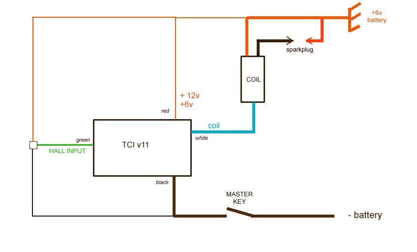
Hello,
Is it possible to order this product already programmed with the advance curve for a 1986 yamaha 600 XTZ (TENERE)? It will save me from buying a PIC programmer at first.
Thank you.
Hi
Nice bike, I had one. It’s less risky if you enter the timing curve and pickup position data yourself. The curve is in the xt600 manual and its a free download:
https://www.manualslib.com/manual/1075942/Yamaha-Xt-600-Ac.html
See P37.
However, It’s TCI not CDI – You can easily convert to CDI with a bit of rewiring and a CDI coil.
Hi,
The manual linked above is about XT600 1990 3UY
AFAIK it’s indeed a TCI whereas JeanFrancois’s is a 1986 (1VJ or 3AJ) = ACCDI
HI
I’ve just tested mine on my Chinese Suzuki carburettor GN250 clone (Bullit, Hunt 250 – Crankshaft Tab offset 75 deg.) Very happy, nice and stable and starts well. Leave a comment here if anybody would like this particular curve data.
I couldn’t get my timing light to work effectively, so I used my double beam oscilloscope to fine trim the curve data pickup position. Note though, this will only really work with a reluctor pickup.
Referring to the schematic: Place one probe on the pickup (at J9 or J10 input). Solder a 4k7 resistor to J6 kill input and ground and attach the other probe. To view timing: Start engine and try running at various rpm, adjusting time/cm to give pulse repetition at 7.2 cm (50 deg./cm). To fine trim curve data pickup position: At low rpm J6 pulse rising edge should coincide with the second reluctor pulse on J9/10 (10 deg. btdc in my case).
Thanks Robert for this feedback and the trick for measuring the advance without timing lamp.
Here is the XLS you used for the Bullit Hunt 250 (GN250 clone)
Hi, Thierry.
Шs it possible to replace the transformer with a toroidal one?
And could you tell me how to find, according to what parameters, the transformer separately?
Hi, It’s not “just” a simple transformer, it has an extra winding to drive the 2 NPN that drive the primary.
I don’t think you can find a toroïdal transformer with same characteristics….
Thank you for answer. Got it.
There is no marking on this the transformer.
All that i could find that this transformer is EE25. But, as i understood, this is ferrite core marking. No any information about coils…
Maybe you know and can tell me an analogue or a link to such a transformer?
https://transmic.fr/product/dc-converter/
Will a EEprom data hex file created in your Excel spreadsheet Version DC-CDI v7.9r5c0 work properly if the 16F1827 PIC has Firmware_DCCDI_16F1827_v7.9R9C3Full or do I have to use a different version of your Excel spreadsheet?
No. Latest firmware uses new options that are only written by latest spreadsheet.
Thank you. I have so many versions I’m not sure what works. The latest I have is Excel Version 16F1827 v7.9r25c1 Will this work with Firmware_DCCDI_16F1827_v7.9R9C3 If so, I’ll try that. That firmware is supposedly on the last two kits I bought from you.
Hi, THIERRY.
I assembled cdi according to the scheme, only instead of the PIC controller, the arduino controller. The problem is, after applying a control signal to the thyristor, only one spark passes. I think the thyristor remains open. Is the P3-C7 chain responsible for closing? Or is it a software error … Maybe i need to turn off the converter after each spark to remove power from the thyristor? Can you give advice?
>I think the thyristor remains open.
Yes
> Is the P3-C7 chain responsible for closing?
no
>i need to turn off the converter after each spark to remove power from the thyristor?
not after, but BEFORE
Thank you very much, I will try.
Hi, Thierry.
I fixed the software and it still didn’t work. Then I replaced the capacitor. It was 1 microfarad 270v, I changed it to 1.5 microfarad 400v. Now there is a spark.
Btw, my converter produces ~400 volts instead of ~270.