No more OEM? No Problem!
Custom Ignition Solutions for Your Classic Bike!
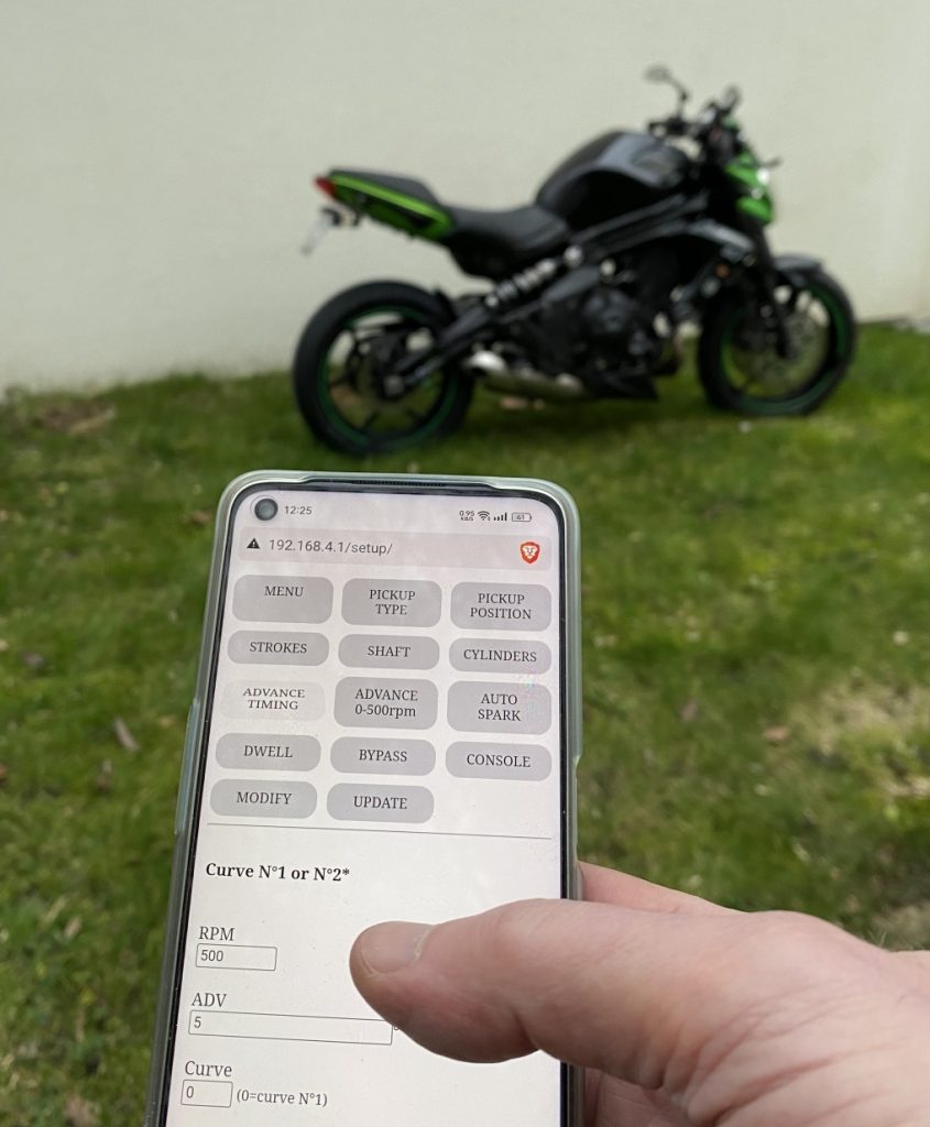
This technology will make your motorcycle tuning much simpler and faster.
Just connect your phone to your motorcycle and you’re ready to go!
A programmable ignition is extremely valuable in repair work as it fits a wide range of bikes.
It’s especially useful if the original part has been discontinued or is overpriced.
And of course it’s a must-have if you are wishing to tune the engine.
This is not a Plug’n Play device!
You provide the characteristics of your engine, the ignition provides the possibilities. The final result depends on the settings you choose.
Programmable TCI.

Features
- Wireless Programmable TCI.
- Suitable for ONE or TWO* cylinders
- For [2 strokes engines] and for [4 strokes engines with wasted spark]
- Easy programming via WiFi connection. (No cable)
- You need a simple web browser on any smartphone or laptop. (No app)
- Compatible Windows, Android, Mac, Linux (No special OS).
- Non volatile configuration.
- ONE or TWO programmable ignition timing curves. *
- Rev from 10 to 10,000 RPM. [Up to 20k with a High Performance Ign. coil]
- Adjustable timing in 13 steps from 500 to 20,000RPM.
- Retarded advance from 1 to 500 RPM to avoid kickbacks.
- Rev limiter.
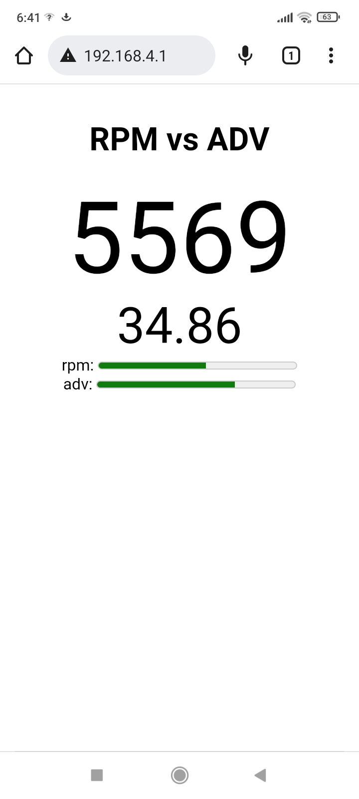
- Live Display of RPM and Timing via Wifi.
- 1 input for an inductive pickup (VR).
- Support 2 Pickup polarities. (Positive or Negative first). New !
- 1 input for an Hall Effect Sensor or Points. *
- 1 output for an INDUCTIVE coil type from 1.5ohm to 5ohm.
- Adjustable Dwell.
- 1 input for Kill switch.
- 1 input to select Timing N°1 or N°2 at startup. *
- 1 input for Security switch(es) or for a Quick Shifter * New !
- 1 input for a Quick Launch or a Rev-limiter switch. * New !
- 1 output for 12v Tachometer signal. *
- IGBT Coil driver.
- Coil Overvoltage: Max 430v
- Power supply voltage: 10 to 16Vdc battery.
- Coil current: Max 15A
- Quiescent current 30mA.
- Coil protection: Shut off after 1sec without pickup signal.
- Current with ignition coil: 4 to 8A peak/1-2A avg.
- Protected against reverse supply voltage.
- Dimensions: 75 x 70 x 25mm (2.95 x 2.75 x 1inch) 150gr (5.3oz)
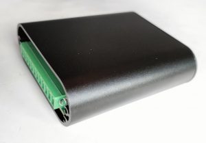
- Strong Aluminum box.
- Potted for Electrical insulation.
Protecting components from mechanical shock and vibration, thermal shock or moisture. - 300V 8A 12pins connector.
- 6 months Warranty + LifeTime Firmware Updates. New ! *
- Made in France.
* Options
Cylinders
Single-cylinder:
If there is one separate pickup:
=> This TCI works.
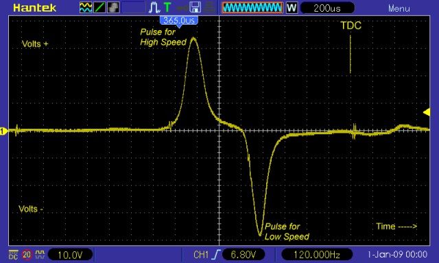
If there are 2 separate pickups (one for low RPM and one for High RPM):
=> This TCI works and uses only the High RPM pickup.
If the engine works with Missing Teeth:
=> This TCI will NOT work
* Twin-cylinders at 360° crankshaft angle:
The engine works with WASTED spark.
If there is ONE twin coil:
=> This TCI works.
See: TCI compatibility
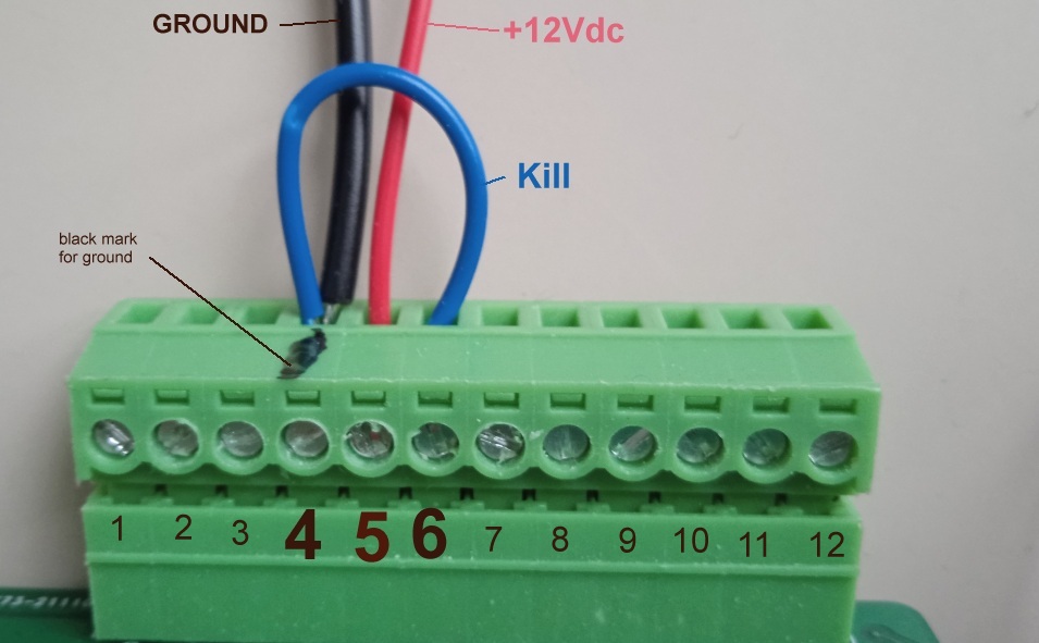
WIRING
Pin 4 is the black mark
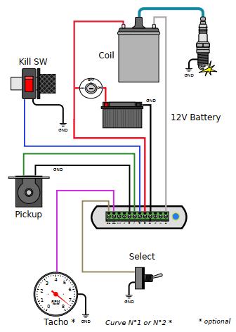
12 pins connector
With Hall Sensor
HowTo wire Sidestand & Neutral switches on XT550/XT600/TT600
Setup for Suzuki Savage LS650.pdf
How To setup
To program the ignition, please Print and follow this procedure:
The 12pins connector has a marker trace on pin4 which is Ground.
1) Connect a Black wire from connector pin4 to the black plug of a 12v battery.
2) Wire a bridge between connector pins 4 and 6 (ground and kill input).
3) Connect a Red wire from +12v connector pin5 to the red plug of the battery to power up the ignition.
4) Led blinks 5 times while a WiFi Access Point named “Transmic_ign” show up on you laptop/smartphone.
(If a password is asked, use “password”)
COIL
TCI ignitions need an INDUCTIVE coil type for TCI (Not a CAPACITIVE coil for CDI)
Ignition coils are different from TCI to CDI systems. Why CDI coils don’t work with TCI ignitions?
– CDI coils have low inductance (L=0.1 to 0.7mH) and primary resistance of around 0.3 to 0.8ohm
– TCI coils have higher inductance (L=4 to 15mH) and primary resistance of around 1 to 5ohm
(1ohm for electronic ign./ 3ohms for transistorized ign./ 5ohms for points ign.)
Energy on Primary side = I * I * L / 2 so the higher inductance the better.
TCI coils: IMFsoft, Ignitech, Ignitech 3ohms, Ignitec 1ohm, AEM, Bosh High Energy, Double coil, Honda Double coil, Suzuki Double coil,
Pickup coil
A pickup (aka: VR, Variable Reluctor, Reluctor, Trigger coil, Magnet) is a sensor with one signal and one ground line.
It consist of a wire coiled around a magnet. When a ferrous object passes by the magnet, the magnetic field is modified and a voltage pulse is generated in the coil, resulting in a sine wave.
– Inductive pickup MUST give 1 signal per crank revolution.
– Pickup MUST put out 3 to 50Vac
– This TCI works with ONE pulse per rev. 1 pickup and 1 reluctor (the metal strip on the flywheel) [“A” or “B” below].
– This TCI works with 2 pickups and 2 bars [E,F].
– This TCI DOES NOT work with multi-pulses pickup (ie 2 reluctors on the flywheel) [C,D].
– This TCI DOES NOT work with a missing tooth flywheel [G].
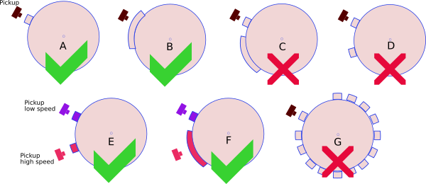
This ignition works with all Chinese pickup sensor like this one.
Pickup Position
“Pickup Position” is the number of degrees between the very first pulse from the pickup and TDC
To be able to provide the largest advance timing (Example 36° @ 4500rpm) the pickup MUST send a trigger signal BEFORE the piston reaches 36° before top dead center (BTDC).
The “Pickup Position” on the Yam XT600 is 50°.
Many Yamahas have a “Pickup Position” of 72 degrees.
This “Pickup Position” depends on:
– Where the pickup is mechanically located with respect to TDC?
– Where is the flywheel’s bar located?
– How long is the flywheel’s bar?
“Pickup Position” is always superior or equal to “Max Advance”.
“Max Advance” = “Base Advance” + “Flywheel’s bar Length”
“Base Advance” value is often written in the User Manual.
Length of the flywheel’s bar can be measured this way.
You may measure the “Pickup Position” using a protractor or with a caliper and some math.
Pickup Polarity
A pickup has 2 wires.
– If you ground wire number 1, wire number 2 will put out a Positive pulse first when the rising edge comes, then a Negative pulse when the falling edge leaves. I call it PN.
– If you ground wire number 2, wire number 1 will put out a Negative pulse first, then a Positive pulse. I call it NP.
If the polarity is Negative then Positive(NP) then the leads are backward, if possible just swap the wires to change the pickup polarity !
Even if this TCIv14 can use both polarities, please favour PN Polarity when possible.
Check the polarity of the pickup: Negative going then Positive/NP or the opposite PN: Positive going then Negative, with a Needle galvanometer (in milliAmp position) while kicking.
Pickup Voltage
The higher the RPM, the more voltage it must gives out.
Formula : Minimum Pickup voltage = RPM/1000 + 3
Examples :
At 6000rpm the VR pickup must put out : 6000/1000 = 6 + 3 = 9Vpp (Volts peak to peak)
At 1000rpm the VR pickup must put out : 1000/1000 = 1 + 3 = 4Vpp
Hall Effect Sensor, Contact Breaker/Points
– By default you can use a VR (Variable Reluctor Pickup) or Points.
– If you pay for the “Hall Sensor Input” option, you can use a Hall Sensor or an Optical Sensor (VR is still available).
– Points, reluctors, Hall sensors, optical sensors MUST provide only 1 pulse per revolution.
– Work with NPN Models :
NJK-5002C (70°)
Hamlin 55100 (100°)
Allegro A1101-A1104 (70°)
Allegro old 3141-3144
AiM Hall 712 (70°)
ChipSense AN1V50 (150°)
Littelfuse 55075-00-02-A (125°)
Haltech Honeywell 1GT101DC, SS495, SS49E etc…
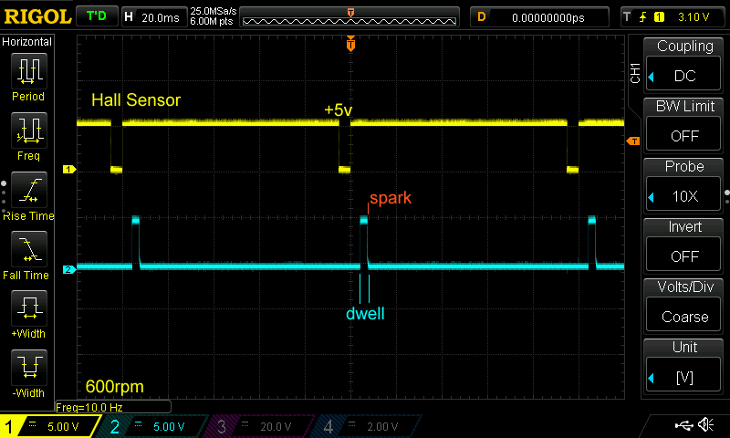

Live Display of RPM vs Timing via Wifi
For diagnostic or tuning purpose, it’s possible to live view RPM and Timing in degrees BTDC on a remote PC connected through Wifi: Video
Because of the impact on TCI performance, please use it for debug only and disable this function when you are done with it!
Ignition timing
Windows software: Interactive_Graph.exe
(Extract this software to where it has read/write permission, i.e. in your Document folder)
Tip: No need to use all 13 points if the curve is straightforward.
Just use the first 2 or 3 timing pairs ! The ignition box will process that faster.
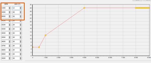
Rev Limiter
The last RPM value you enter is the “rev limit” that stop all sparks.
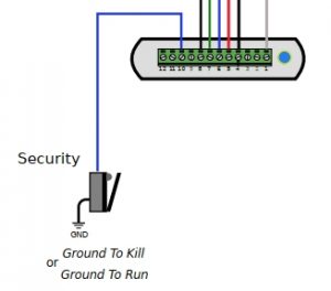
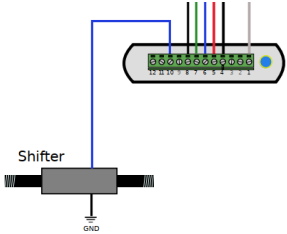
Security/Shifter
The Switch can be one of those 2 type: Gnd2Run or Gnd2Kill
It’s possible to connect more switches of the same type in parallel.
or a Shifter adjustable from 10 to 200ms.
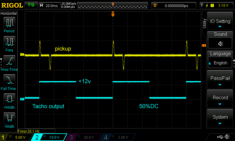
Tachometer
Optional
An output for connecting a digital Tachometer is available.
Output signal is a 0 to +12volts square signal:
AutoSpark
If “Auto-Spark” mode is set to 1/ON during Setup then once the TCI is powered on in “Run” mode, it automatically drives the coil at 300 to 10,000RPM without the need of any pickup.
Pickup can be disconnected.
0 = disable.
Bypass.
/!\ Don’t use the function on a running engine otherwise the spark will append way too soon and could damage the piston !!
But along with points and mechanical advance system, TCI in Bypass Mode is acting as a simple Transistorized Ignition.
Diagnose with LED
– If the box is started in RUN Mode and you have selected Curve N°1: The Led light up 1 time then stays Off.
The led blinks in time when a pickup signal is detected.
– If the box is started in RUN Mode and you have selected Curve N°2: The Led light up 2 times then stays Off.
The led blinks in time when a pickup signal is detected.
– If the box starts in SETUP Mode : Led blinks 5 times fast, 2 seconds off, blinks 5 times fast again, then flashes once every 5 seconds. (See video)
The led flashes briefly when data reaches the box through WIFI.
– In RUN mode, the led flashes every 2 pickup signals.
TCI Troubleshoot.
Test the whole unit
– Remove ALL wires except the coil and the power line.
– REBOOT the ignition to ensure it is in RUN mode. (Not Setup mode): See video
Update Firmware.
Keeping your box up to date.
– If you bought the Warranty + 1 Year Update Option, you can update the ignition firmware whenever an update is available.
Please refer to “How to Setup” above, to know how to do it.
Understanding update status with led (video)
VERSIONS
- Version v14r0c0:
- [Hard] Smaller unit
- [Hard] Strong Aluminium box
- [Hard] Can use both pickup polarities
- [Soft] Optional Firmware update
- Version v14r1c0:
- [Hard] Add Security Switch
- Version v14r2c0:
- [Soft] Fix reboot during display of HTML page
- [Soft] Change in HTML page
- Version v14r3c0:
- [Hard] Add Shifter input
- [Soft] Change in HTML page
- [Soft] Timing @500rpm is now 30° max
- [Soft] Fix reboot during Dump display
- Version v14r4c0:
- [Soft] Bug fix when Pickup on camshaft
- Version v14r5c0:
- [Soft] Reduce memory usage
- Version v14r6c0:
- [Soft] Start RPM is now 150
- [Soft] Code Hardening
- [Soft] Reduce memory usage
- [Soft] Improve Wifi stability
- Version v14r7c0:
- [Soft] Reduce code
- [Soft] Cut coil after 500ms without pickup
- Version v14r8c0:
- [Soft] Timing curve adjustable from 200rpm
- [Soft] New feature to ease engine start
- [Soft] Autospark tests all rpm in one shot
- [Soft] Add html page to check eeprom content
- [Soft] Improved and faster GUI
- [Soft] +18% Faster code
- [Soft] Code Hardening
- [Soft] Bug fix on Dwell time
- Version v14r9c0:
- [Soft] Code cleaning
- Version v14r10c0:
- [Soft] Correction in advance calculation
- [Soft] New console display with RPM graph
- Version v14r11c0:
- [Soft] Bug fix for Shaft pickup
- [Soft] Add QuickLaunch/rev-limiter feature
PHOTOS
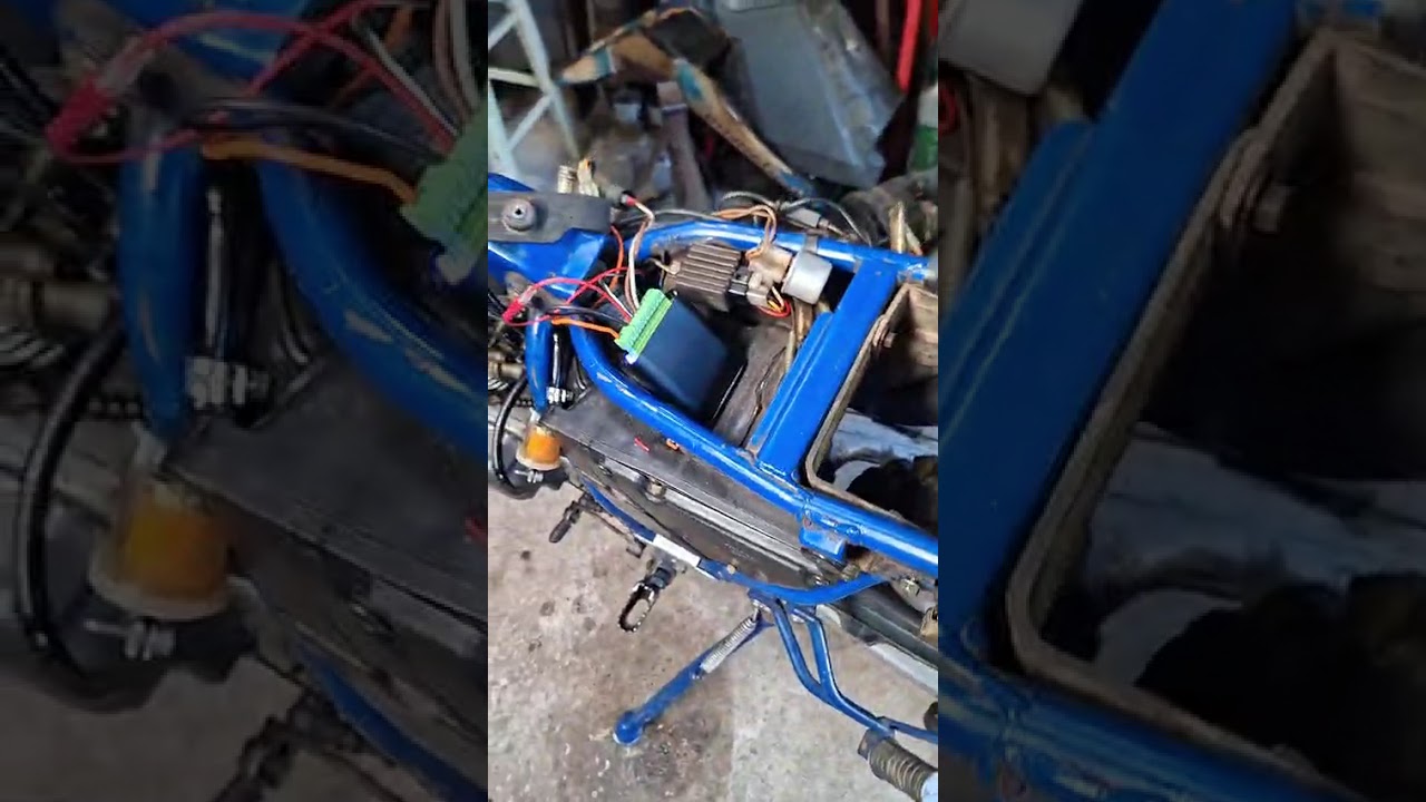
A 1998 TT600E converted to TCIv14 (Danemark)

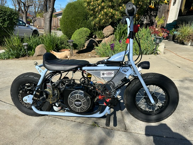
@Justin Bet Retromod Garage fitted a TCIv14 in one of his Mini Cruiser Bike. (USA)
Legal Eagle XL airplane with half VW engine. Twin cylinder, 4 strokes. 3ohm Harley Sporster coil, Hall sensor + TCIv12. (USA)
![]()
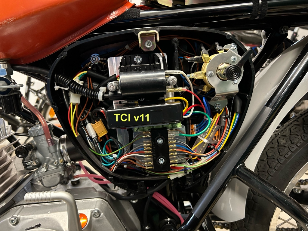
A 1981 Simson S51B 110cc 1cyl 2stk converted from HPI 210 programmable CDI to RZT-Delta-21 and TCIv11 to suppress kickbacks with HPI. (Germany)

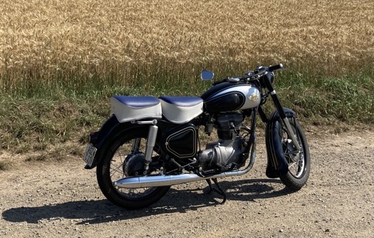
A 1959 Simson 425S 250cc 1cyl 4stk converted from Magneto to TCIv10 (Germany)
Scope trace:
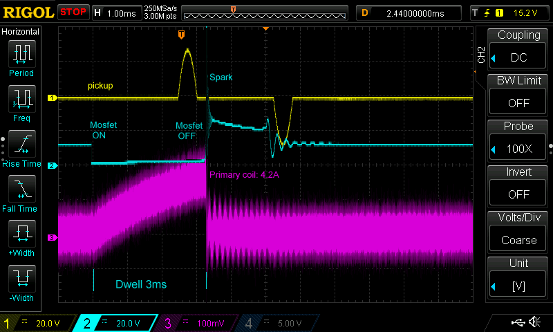
Current drawn depending on the coil resistance and Dwell time. Ie for 1ohm and 3ms.
VIDEOS
BBBikeshop.co.uk converted a Yamaha XT225 to a TCIv14 (UK):
A 1972 Kreidler Florett 50cc 1cyl 2stk with rotary valve and TCIv14 Max: 16HP and 13500rpm (Sweden)

A Yamaha XT600E 4LW converted to TCIv14 (New Zealand):
BBBikeshop.co.uk converted an Husqvarna SM610 to a TCIv14 (UK):
BBBikeshop.co.uk adapted TCIv12 to an Honda CB400N. (UK):
“In 2024 there will be a complete CDI to TCI replacement plug and play system for these Honda 400/450 twins that will include an Inductive HT coil, replacement purpose made pickup trigger coil, direct plug in wiring to the bikes existing loom.” More detail on his FB page.
TCIv12 driving HD Sportster ignition (USA):
TCIv11 setup for Sanglas 400E (Spain):
Simson S51B + TCIv11 (Spain)
Sanglas 400E + TCIv11 + Analog pickup (Spain)
Sanglas 400E + TCIv11 + Hall sensor (Spain)
Bench test (USA):
Yamaha XS650 + TCIv11 (USA):
Hall Sensor vs Reluctor:
Do you have an idea of the current draw from around 2,000 to 8,000 rpm?
It depend on the ignition coil. I added a snapshot above at “Photos”
True. This is how I see things: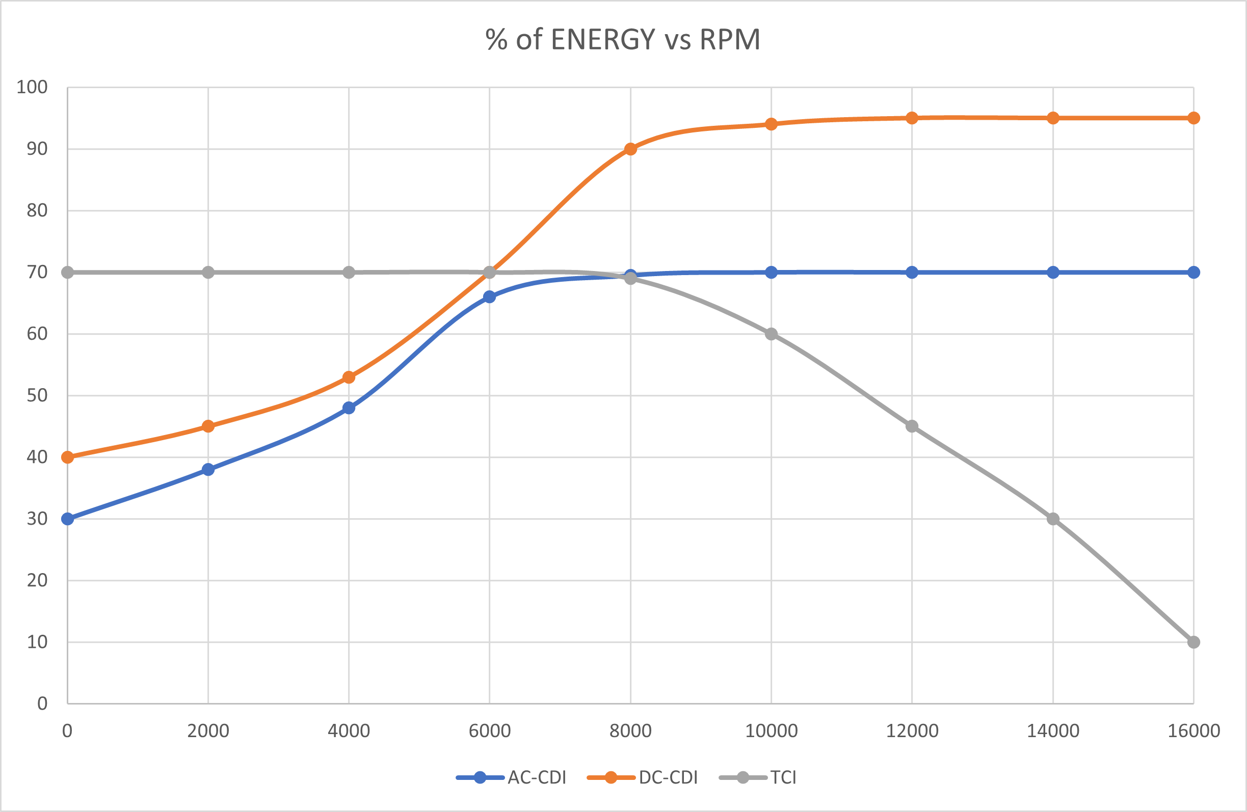
>You also said to use an inductive coil. Would this coil be a standard automotive type of 1 to 5 ohms primary resistance?
Indeed.
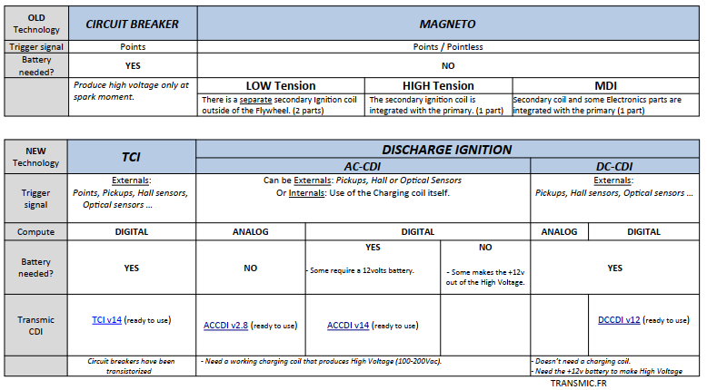
Thank you for the graph comparing the three systems.
True. This is how I see things: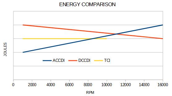
>You also said to use an inductive coil. Would this coil be a standard automotive type of 1 to 5 ohms primary resistance?
Indeed.
Thank you for the graph comparing the three systems.
I’ll be using an Allegro A1104 Hall effect sensor as the pickup on the TCIv12 just ordered from you. It has an internal voltage regulator. You mentioned a pull up resistor. What value do you recommend, or is it needed on this particular sensor?
I left off part of my question. Should the pull up resistor go between VCC and the output signal pins on the A1104?
You should find answers by reading the documentation .PDF above 😉
>To program the ignition, please Print and follow this procedure: Setup Ignition box.pdf
Will do. Thanks!
hello.
first off, wonderful device. reliable and easy when you get it all dialed in.
im attaching my values for a suzuki savage 1999.
should work with all years of this model .
hope it helps someone .
Hi Thierry-
We have a 1991 Yamaha XT600E, and purchased your TCIV14. We are having a problem achieving a spark due to lack of pickup coil voltage being produced. The pickup coil resistance is within specification and all wiring is correct.
So far we have bench tested the TCI with a simulated sine wave from a function/ signal generator representing the pickup coil with success, but when wired to the pickup coil on the bike, it will not spark. We built an amplifying circuit for the pickup coil signal using an OP-AMP and boosted the signal to a higher voltage. The output signal from the OP-AMP was enough to illuminate an LED, but was not enough to trigger the TCI interrupt.
Do you have any suggestions? What are we missing?
Thanks! Brian
Hi Brian
I test all my ignition boxes before shipping with a Signal Generator that mimic a pickup signal. So it’s not a sinus wave but it really looks like a real one. Btw your sinus test is still valid.
The TCI or CDI sensitivity is <2volts where a working pickup goes from around 5 to 20v
I personally also had a faulty pickup on mine even if the ohm reading was withing the manual ! The pickup became defective when hot.
A too low signal may come from a too large gap between pkp and magnet or from a "weak" magnet.
I doubt you can provide a good signal from a faulty pickup with an amplifier...
I would compare the signal with a scope to a known-good one, with and without load/TCI.
20$ scopes or DIY scope: https://transmic.fr/2016/07/01/links/
https://transmic.fr/wp-content/scope/interface_soundcard.pdf
Th
Hi Thierry-
Thank you for the insight. I think the best option for us is to install a new pickup coil and test it again. Hopefully the magnets attached to the rotating assembly on the engine are still strong enough (not “weak” like you mentioned) to trigger a new coil, that rotor assembly seems like a difficult part to find!
This project motorcycle came to us missing the TCI, so my son and I are starting from scratch and have never had it running. Hopefully soon! Thanks again.
Cheers, Brian
Any aftermarket pickup will work, like this one: https://www.aliexpress.com/item/4000013985407.html
The hardest part is to fit it in the casing… 🙁
Hi Thierry-
A quick update with a related question. We ended up purchasing a new stator and pickup coil, and installing it in the 1991 XT600E. Unfortunately we STILL do not have a spark. We were however, able to trip your TCI and produce a reliable spark by waving a STRONG magnet in front of the original pickup coil that we now have as a spare. This leads us to believe the magnets on the flywheel/ rotor inside the engine may not be strong enough to trip the TCI via the pickup coil. What do we do in this situation? The rotor is no longer available from Yamaha, a used version seems impossible to find and a gamble. Can magnets be re-energized? Any ideas from your professional perspective?
Thank you in advance-
Brian
Hi Brian,
Magnets slowly demagnetized with time and with high temperature too, that’s why welding a rotor can definitely destroy magnets.
They can be re-magnetized by rubbing the opposite pole of a strong neodymium magnet or by inserting them in the core of a electro-magnet.
Workaround:
Lower the gap between magnet and pickup coil.
Replace the pickup coil with a Hall Effect sensor.
I like to use a “magnetic field viewer” to see hidden magnets….
Th