TCI v12 is End Of Live
Ignition system – Programmable TCI
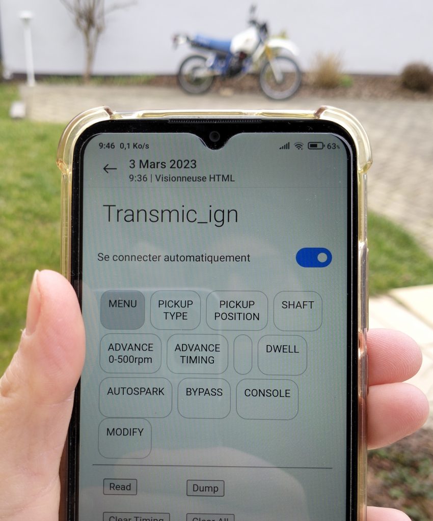
This technology will make your motorcycle tuning much simpler and faster.
Just connect your phone to your motorcycle and you’re ready to go!
A programmable ignition is extremely valuable in repair work as it fits a wide range of bikes.
It’s especially useful if the original part has been discontinued or is overpriced.
And of course it’s a must-have if you are wishing to tune the engine.
Features
- Wireless Programmable TCI.
- Suitable for ONE or TWO* cylinders
- For [2 strokes engines] and for [4 strokes engines with wasted spark*]
* On 4stk engines with a pickup on the crankshaft, one spark occurs during the compression stroke and another during the exhaust stroke.
- Easy programming via WiFi connection.
- You need a simple web browser on any smartphone or laptop. (No app)
- Compatible Windows, Android, Mac, Linux
- 80MHz MicroController control unit
- Firmware included
- Non volatile configuration
- ONE or TWO programmable ignition timing curves. *
- Rev from 10 to 30,000 RPM.
- Adjustable timing in 13 steps from 500 to 20,000RPM.
- 0 deg advance from 1 to 500 RPM to avoid kickback
- Rev limiter.
- Live Display of RPM and Timing via Wifi.
- 1 input for an inductive pickup (VR). Pickup polarity MUST be Positive first.
- 1 input for an Hall Effect Sensor or Points (An external resistor is required) *
- 1 output for an INDUCTIVE coil type from 1.5ohm to 5ohm.
(TCI cannot work with CDI coil)
- 1 input for Kill switch.
- 1 input to select Timing N°1 or N°2 at startup*
- 1 output for 12v Tachometer signal. *
- IGBT Coil driver
- Coil Over Voltage: Max 430v
- Coil current: Max 15A
- Coil protection: Shut off after 1sec without pickup signal.
- Power supply voltage: 6 to 16Vdc battery.
- Quiescent current 30mA
- Protected against reverse supply voltage.
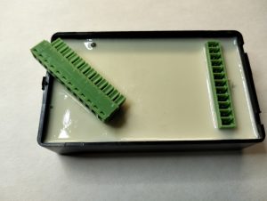
- Dimensions: 100 x 60 x 25mm (3.9 x 2.4 x 1inch)
- Plastic box potted for Electrical insulation, Protecting components from mechanical shock and vibration, thermal shock or moisture.
- 300V 8A 12pins connector.
- Made in France.
* Options
Cylinders
Single-cylinder:
If there is one separate pickup:
=> This TCI works.
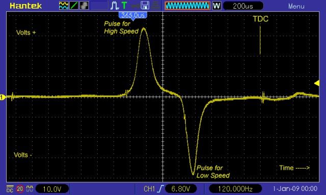
If there are 2 separate pickups (one for low RPM and one for High RPM):
=> This TCI works and uses only the High RPM pickup.
If the engine works with Missing Teeth:
=> This TCI will NOT works
* Twin-cylinders at 360° crankshaft angle:
The engine works with WASTED spark.
If there is ONE twin coil:
=> This TCI works.
See: TCI compatibility
WIRING
Pin 4 is the black mark
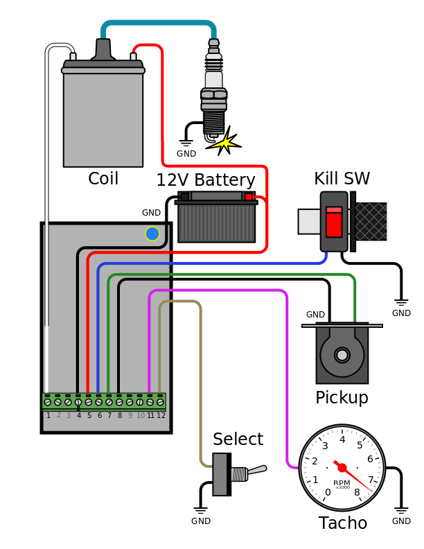 12 pins connector
HowTo wire Sidestand & Neutral switches on XT550/XT600/TT600
How To setup
To program the ignition, please Print and follow this procedure: Setup Ignition box TCIv12r7c1.pdf
Old manuals:
Setup TCIv12r1c2.pdf
Setup TCIv12r1c1.pdf
Setup TCIv12r0c1.pdf
Setup TCIv12r0c0.pdf
Settings:
Setup for Suzuki Savage LS650.pdf
Pickup coil
A pickup (aka: VR, Variable Reluctor, Reluctor, Trigger coil, Magnet) is a sensor with one signal and one ground line.
It consist of a wire coiled around a magnet. When a ferrous object passes by the magnet, the magnetic field is modified and a voltage pulse is generated in the coil, resulting in a sine wave.
– Inductive pickup MUST gives 1 signal per crank revolution.
– Pickup MUST puts out 3 to 30Vac
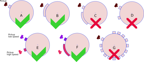
– This TCI works with ONE pulse per rev. 1 pickup and 1 reluctor (the metal strip on the flywheel) [“A” or “B” below].
– This TCI works with 2 pickups and 2 bars [E,F].
– This TCI DOES NOT work with 1 pickup and a multi-pulse pickup (ie 2 reluctors on the flywheel) [C,D].
– This TCI DOES NOT work with 1 pickup and a missing tooth flywheel [G].
Pickup Position
“Pickup Position” is the number of degrees between the very first pulse from the pickup and TDC
To be able to provide the largest advance timing (Example 36° @ 4500rpm) the pickup MUST send a trigger signal BEFORE the piston reaches 36° before top dead center (BTDC).
The “Pickup Position” on the Yam XT600 is 50°.
Many Yamahas have a “Pickup Position” of 72 degrees.
This “Pickup Position” is dependent on:
– Where the pickup is mechanically located with respect to TDC?
– Where is the flywheel’s bar located?
– How long is the flywheel’s bar?
“Pickup Position” is always superior or equal to “Max Advance”.
“Max Advance” = “Base Advance” + “Flywheel’s bar Length”
“Base Advance” value is often written is the User Manuel.
Length of the flywheel’s bar can be measured this way.
You may measure the “Pickup Position” using a protractor or with a caliper and some math.
Pickup Polarity
When the bar/magnet on the flywheel passes in front of the pickup, the pickup generates two pulses of OPPOSITE polarity.
A pickup has 2 wires. If you ground wire number 1, wire number 2 will put out a Positive pulse first when the rising edge comes, then a Negative pulse when the falling edge leaves. I call it PN.
If you ground wire number 2, wire number 1 will put out a Negative pulse first, then a Positive pulse. I call it NP.
Pickup Polarity MUST be Positive then Negative to work with this TCI.
Check the polarity of the pickup (Negative going then Positive/(I call it NP) or the opposite PN: Positive going then Negative) with a Needle galvanometer (in milliAmp position) while kicking.
If the polarity is Negative then Positive(NP) then the leads are backward, just swap the wires to change the pickup polarity !
Watchout! If the pickup is internaly grounded and output ONLY one wire, you won’t be able to change the polarity.
So if the polarity is NP (Negative first) then you CANNOT use this ignition!
Hall Effect Sensor, Contact Breaker/Points
Optional
– Points, reluctors, Hall sensors, optical sensors can also be used as long as they give only 1 pulse per revolution. They may need an additional pullup resistor.
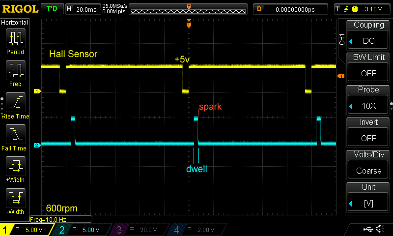
– 3 wires digital Hall effect sensors need an external pull-up resistor. The default voltage output is equal to Vcc (+5v to 24v). When a magnet passes in front of the sensor, the output voltage goes low and the ignition will detect the RISING edge meaning the trigger moment will be when the magnet LEAVE the sensor.
Models : Hamlin 55100, Allegro A1101-A1104, Allegro old 3141-3144, Honeywell 1GT101DC, SS495, SS49E etc…
Pullup resistor: 370ohm (270 to 1200ohm)

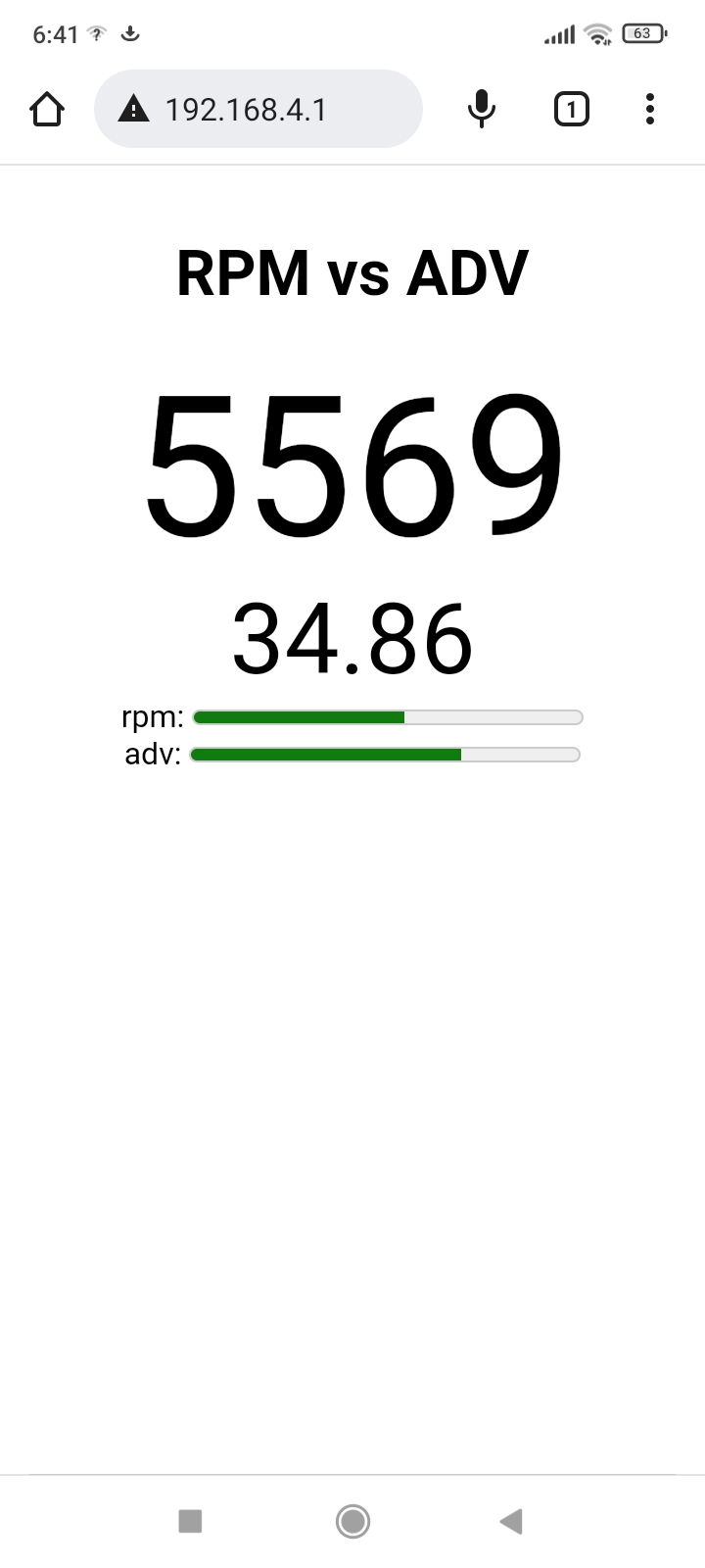
Live Display of RPM vs Timing via Wifi
For diagnostic or tuning purpose, it’s possible to live view RPM and Timing in degrees BTDC on a remote PC connected through Wifi: Video
Because of the impact on TCI performance, please use it for debug only and disable this function when you are done with it!
Ignition timing
– Draw the ignition timing curve into this XLS sheet.
Rev Limiter
The last RPM value you enter is the “rev limit” that stop all sparks.
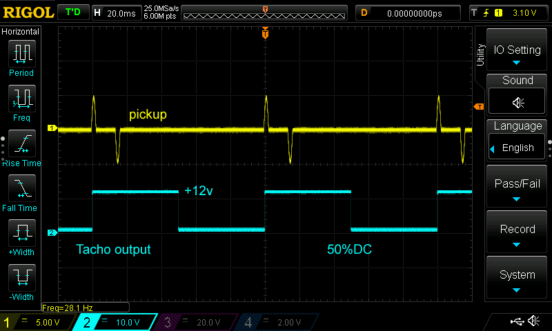
Tachometer
Optional
An output for connecting a digital Tachometer is available.
Output signal is a 0 to +12volts square signal:
AutoSpark
If “Auto-Spark” mode is set to 1,2,3 or4 during Setup then once the TCI is powered on, it automatically drives the coil at 300 to 10,000RPM without the need of any pickup.
Pickup can be disconnected.
0 = disable.
Bypass.
/!\ Don’t use the function on a running engine otherwise the spark will append way too soon and could damage the piston !!
But along with points and mechanical advance system, TCI in Bypass Mode is acting as a simple Transistorized Ignition.
Diagnose with LED
– If the box is started in RUN Mode and you have selected Curve N°1: The Led flashes 1 time then stays Off.
The led blinks in time when a pickup signal is detected.
– If the box is started in RUN Mode and you have selected Curve N°2: The Led flashes 2 times then stays Off.
The led blinks in time when a pickup signal is detected.
– If the box starts in SETUP Mode : Led blinks 5 times fast then flashes once every 5 seconds.
The led flashes briefly when data arrives through WIFI.
COIL
TCI ignitions need an INDUCTIVE coil type for TCI (Not a CAPACITIVE coil for CDI)
Ignition coils are different from TCI to CDI systems. Why CDI coils don’t work with TCI ignitions?
– CDI coils have low inductance (L=0.1 to 0.7mH) and primary resistance of around 0.3 to 0.8ohm
– TCI coils have higher inductance (L=4 to 15mH) and primary resistance of around 1 to 5ohm
(1ohm for electronic ign./ 3ohms for transistorized ign./ 5ohms for points ign.)
Energy = L * I * I so the higher inductance the better
TCI coils: IMFsoft, Ignitech, Ignitech, AEM.
PHOTOS
Legal Eagle XL airplane with half VW engine. Twin cylinder, 4 strokes. 3ohm Harley Sporster coil, Hall sensor + TCIv12.
![]()
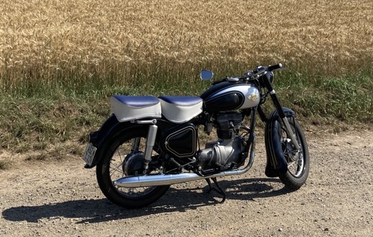
A 1959 Simson 425S 250cc 1cyl 4stk converted from Magneto to TCIv10:
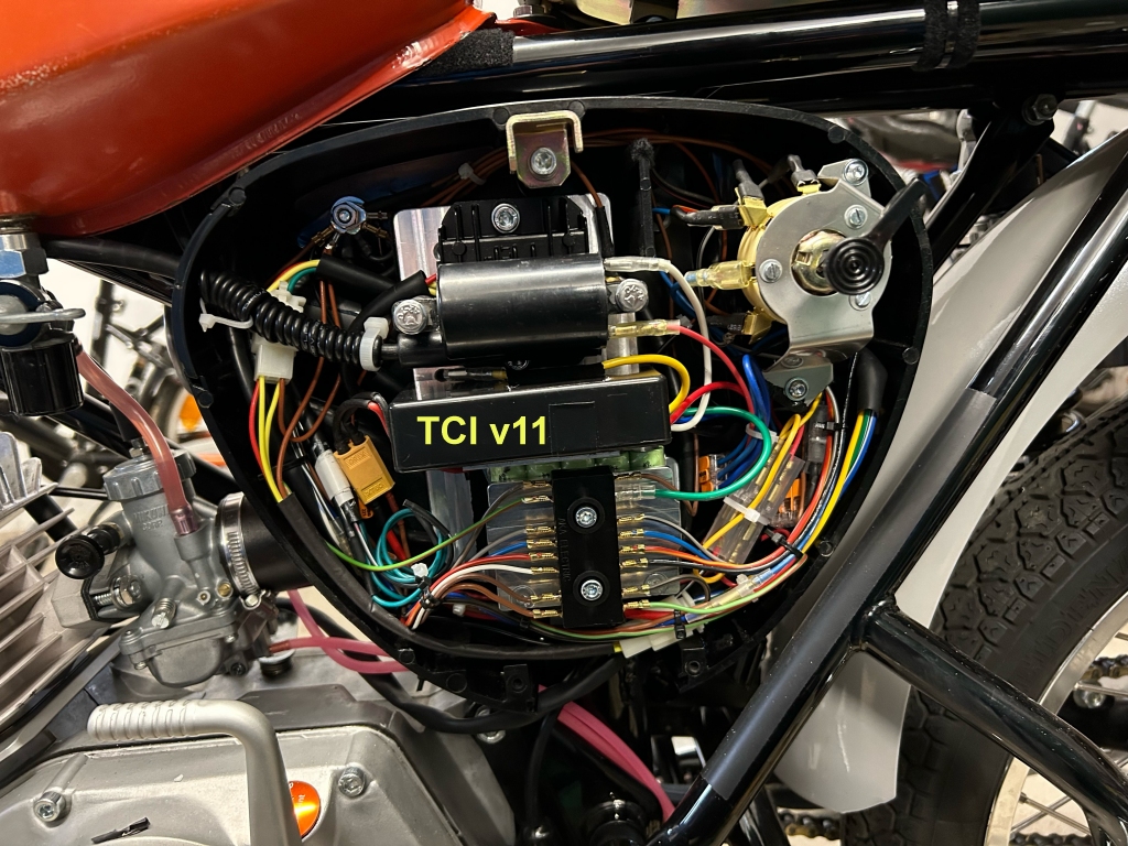
A 1981 Simson S51B 110cc 1cyl 2stk converted from HPI 210 programmable CDI to RZT-Delta-21 and TCIv11 to suppress kickbacks with HPI:

Scope trace:
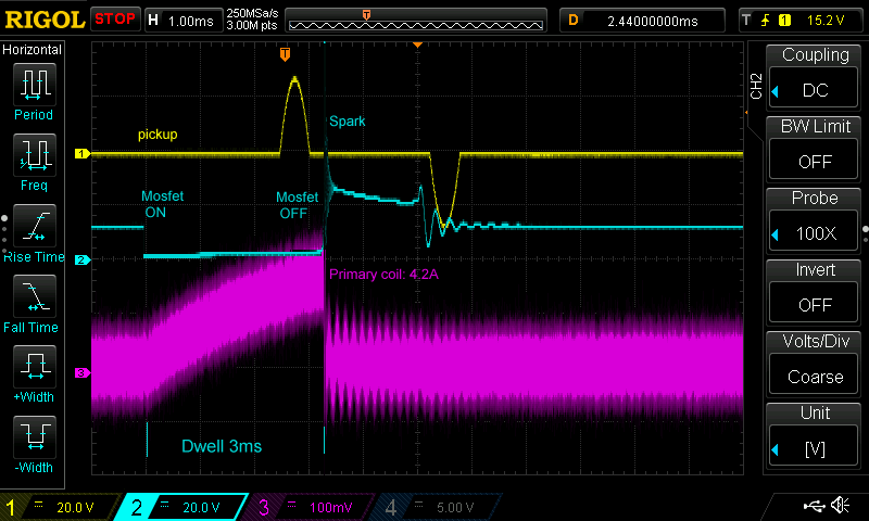
Current drawn depending on the coil resistance and Dwell time. Ie for 1ohm and 3ms.
VIDEOS
VERSIONS
- Version v12r0c0:
- [Hard] Replace wires by connector
- [Hard] Add a VR conditioner for noisy environment
- [Hard] Add Hall Effect Sensor input
- [Soft] 2 Curves available
- [Soft] HTML form changed
- Version v12r3c0:
- [Soft] Wifi stability improved
Do you have an idea of the current draw from around 2,000 to 8,000 rpm?
It depend on the ignition coil. I added a snapshot above at “Photos”
I noticed in another ignition comment section you recommend a TCI ignition instead of a CDI for a slower revving engine 4-stroke. You also said to use an inductive coil. Would this coil be a standard automotive type of 1 to 5 ohms primary resistance?
True. This is how I see things: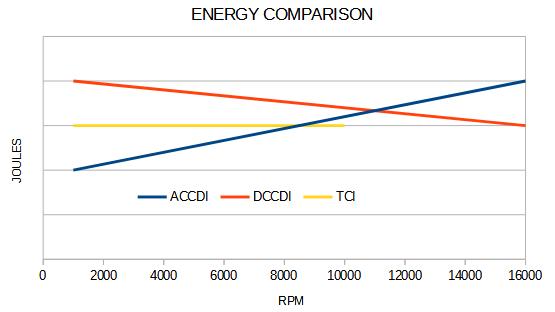
>You also said to use an inductive coil. Would this coil be a standard automotive type of 1 to 5 ohms primary resistance?
Indeed.
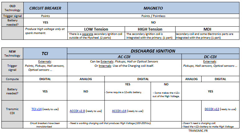
Thank you for the graph comparing the three systems.
I’ll be using an Allegro A1104 Hall effect sensor as the pickup on the TCIv12 just ordered from you. It has an internal voltage regulator. You mentioned a pull up resistor. What value do you recommend, or is it needed on this particular sensor?
I left off part of my question. Should the pull up resistor go between VCC and the output signal pins on the A1104?
You should find answers by reading the documentation .PDF above 😉
>To program the ignition, please Print and follow this procedure: Setup Ignition box.pdf
Will do. Thanks!