This AC-CDI is End Of Live
Repair your vintage motorcycle with this ignition!
Affordable and easy to install, it fits a wide range of models, boosting reliability.
| Easier | Every function has its own DIP Switch. No jumper to cut or to solder. |
| Universal | More DIP Switches to adapt to different engines. 2 trimmers to adjust timing. |
| Safe | 2 types of input to stop the ignition: Ground to Kill and Power to kill. |
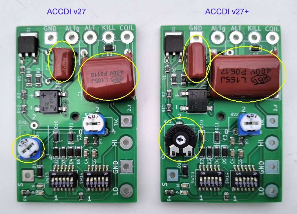
| Powerful | V27: For 50 to 350cc engine with a 1uf capacitor. V27+: 50% more energy for bigger engine from 350 to 800cc with a 1.5uf capacitor. |
| Reliable | V27+: High quality trimmer. (Piher, European brand) High voltage ranking capacitors. (400volts) |
WIRING
COMPATIBLES BIKES
SETTINGS
List of bikes with 1 pickup this CDI works on.
List of bikes with 2 pickups this CDI works on.
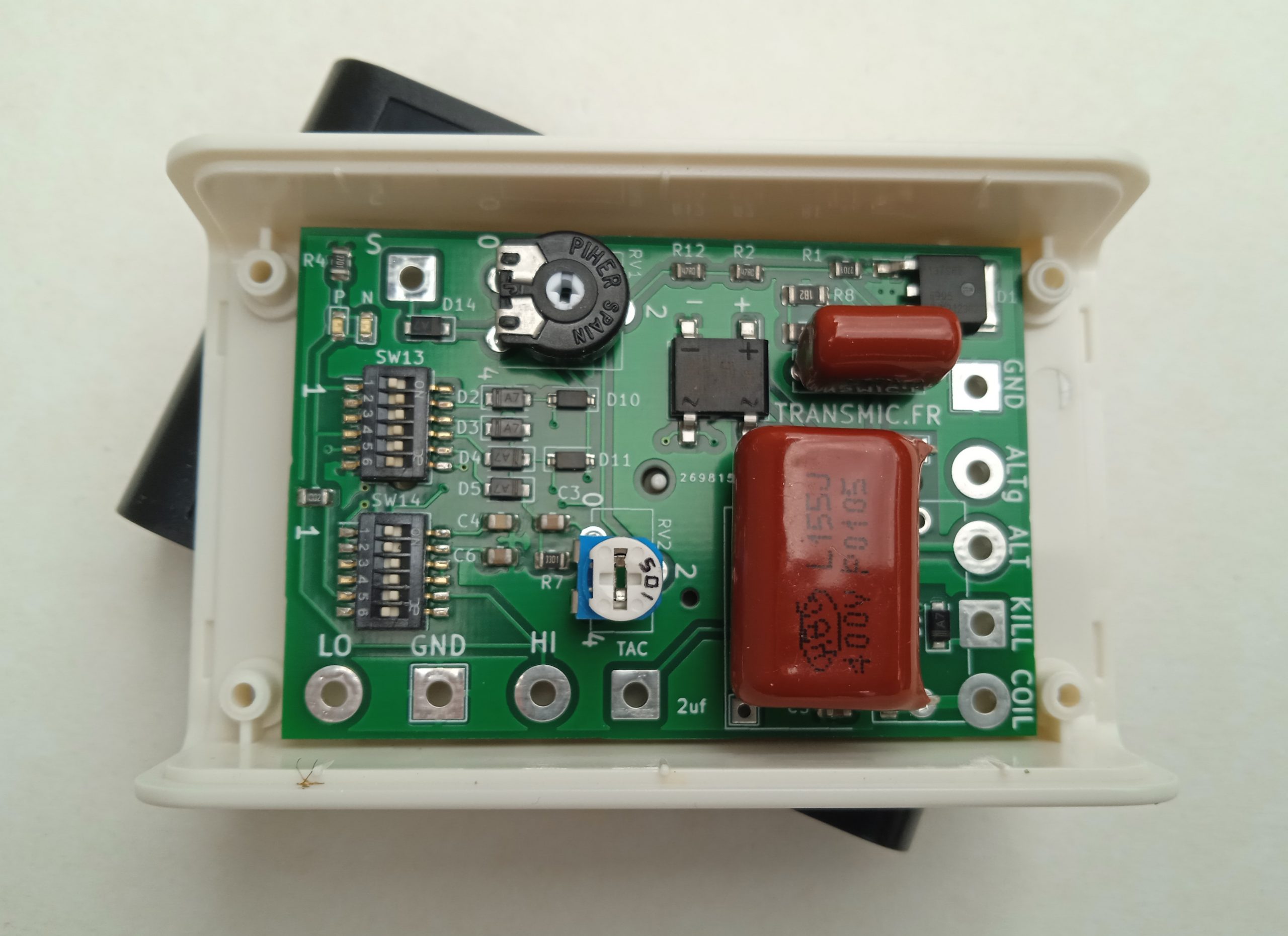
BOX
Drill the cover to pass the wires.
Once you are done for ever with settings, pour the box with PU resin or silicon sealant to make it waterproof.
Fill up the wiring hole with hot glue.
This ACCDI fits in this IP54 box.
IP54 rating means protected against solid objects and dust but is not fully dust tight (5 out of 6).
and protected against water splashing from any angle but not waterproof (4 out of 6)
How does it works?
On an ACCDI based engine, the charging coil (AKA stator) puts out:
– LV (Low Voltage of around 12Vac) for light and battery if any. (Lighting coil)
– HV (High Voltage of around 100Vac) to charge the ACCDI. (Charging coil)
This AC-CDI only uses the HV coil to charge a capacitor through a rectifier bridge.
When the pickup is triggered, the CDI turns on a thyristor that discharge the capacitor inside the primary of the ignition coil.
This burst of energy into the primary induces a high voltage of few thousand volts into the secondary wiring of the ignition coil, enough voltage to create a spark at the sparkplug contacts.
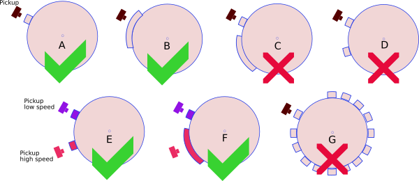
PICKUP
– This CDI works with 1 pickup and 1 reluctor (the metal strip on the flywheel) [A,B].
– This CDI works with 2 pickup and 2 bars [E,F].
– This CDI DOES NOT work with 1 pickup and multi-pulses pickup (ie 2 reluctors on flywheel) [C,D].
– This CDI DOES NOT work with 1 pickup and missing tooth flywheel [G].
– When the engine has only ONE pickup, the 2 wires are connected to HI and GND inputs.
– When the engine has TWO pickups (for Low speed and High speed), the 3 wires are connected to HI, LO and GND inputs.
Pickup Polarity
– When the rising edge of the bar on the flywheel comes in front of the pickup, a pulse is generated.
This first pulse is used by the CDI to spark at high revs.
– When the falling edge of the bar on the flywheel leaves the pickup, another pulse of opposite polarity is generated.
This second pulse is used by the CDI to spark at idle.
A pickup has 2 wires.
– If you ground wire number 1, wire number 2 will put out a Positive pulse first when the rising edge comes, then a Negative pulse when the falling edge leaves. I call it PN.
– If you ground wire number 2, wire number 1 will put out a Negative pulse first, then a Positive pulse. I call it NP.
A genuine Yamaha pickup is often Positive first then Negative (PN) but if you swap the 2 wires of the pickup, the polarity will be Negative then Positive (NP) therefore the DIP switches setting for PN will NOT work anymore of course !
Solution: Rectify the pickup connection or use the settings for NP engines.
Be careful: If the wires are swapped then the pickup polarity will CHANGE !
To find the polarity connect the pickup to an “old” Analogue meter set to it’s lowest voltage setting (around 1volt).
When a non-magnetized steel object (eg a screwdriver) is approached and comes into contact with the top of the magnet the meter needle will indicate a momentary deflection (ie – negative or + positive volts).
When the screwdriver is removed from the magnet’s top the meter needle will show a brief deflection in the opposite voltage. See: Video
HOW TO SET DIP SWITCHES?
You have to know if the bike has 1 or 2 pickups.
Then refer to those lists of settings for bikes with 1pickup or 2pickups
Also you have to know for each pickup what is the polarity:
PN (First pulse Positive then second Negative) or NP (Negative then Positive).
Connect a scope between Ground and pickup wire to check the polarity.
If you don’t have a scope at hand, you can see the polarity with an old voltmeter.
If you still don’t know, you will have to test every possibilities… Follow those guides:
ACCDIv26: Tests all settings for 1 pickup. ACCDIv26: Tests all settings for 2 pickups.
ACCDIv27: Tests all settings for 1 pickup. ACCDIv27: Tests all settings for 2 pickups.
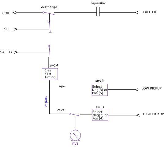
DIP SWITCHES
There are 2 banks of switches SW13 and SW14:

SW13 setting
SW14 setting
2 STROKES
SW14-1, SW14-2: Advance timing
4 strokes engines: set Switches N°1 and 2 of SW14 to OFF (default).
On 2 strokes engines it’s necessary to lower the advance at HIGH RPM:
2 strokes with Small reduction of timing : set Switch N°1 of SW14 to ON.
2 strokes with Medium reduction of timing : set Switch N°2 of SW14 to ON.
2 strokes with Large reduction of timing : set Switches N°1 and 2 of SW14 to ON.

KTM
SW14-3, SW14-4 : KTM setting
All engines, set Switches N°3 and 4 of SW14 to ON (default).
KTM engine, set Switches N°3 and 4 of SW14 to OFF.
SENSITIVITY
SW14-5: pickup Sensitivity
Pickup that puts out 2 to 30volts, set Switch N°5 of SW14 to ON (default).
Pickup that puts out 30 to 150volts, set Switch N°5 of SW14 to OFF.
Sensitivity Fine tuning
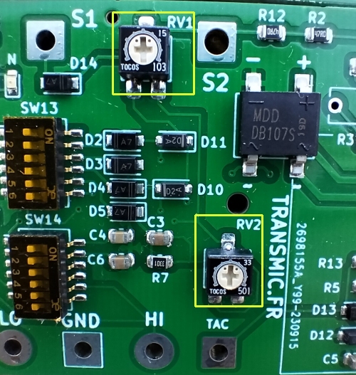
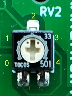
The Sensitivity of the CDI to detect the first pickup pulse (at start and idle) is adjustable with RV2 potentiometer.
– Start the bike with RV2 at max value (4)
– Try different position of RV2 from (4) to (0) to find which position gives the easiest start with no kickbacks.
SW14-6: Not used
Can be on or off.
TIMING ADJUSTMENT
This CDI doesn’t have seamless advance, it jumps from LOW advance to HIGH advance.
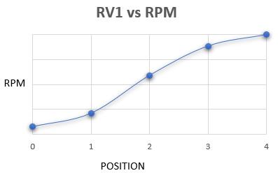
The RPM when the CDI jumps from Low to Full advance (in fact when it switches from the first pickup pulse to the second one) is adjustable with RV1 potentiometer.
– Run the bike at idle with RV1 at max value (4)
– Try to rev up the engine while slowly unscrew (toward 0) until the bikes wants to rev up.
– When she wants to rev up you’ve got the setup.
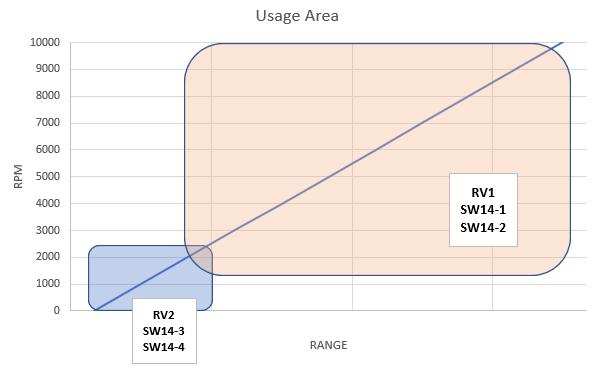
Example:
| 2200 rpm with RV1 at 4: CDI uses the second pulse = Low advance  |
2200 rpm with RV1 at 1.5: CDI uses the first pulse = High advance 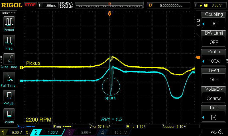
|
INPUTS OUTPUTS
KILL
A Kill switch input is available at “K” header.
Ignition stops when “K” is connected to GROUND.
SAFETY
A Safety switch input “S” is available (for Side stand, Clutch, Neutral, Main switches…)
Ignition stops when “S” is connected to a positive voltage from +2v to +12Vdc.
CHARGING COIL
– If the charging coil is internally grounded, then connect the only wire to “ALT” input and leave “ALTg” not connected. Note that DIP SW13-6 will have no effect.
– If the charging coil is NOT internally grounded, then connect the 2 wires to “ALT” and “ALTg” inputs.
Order has no importance.
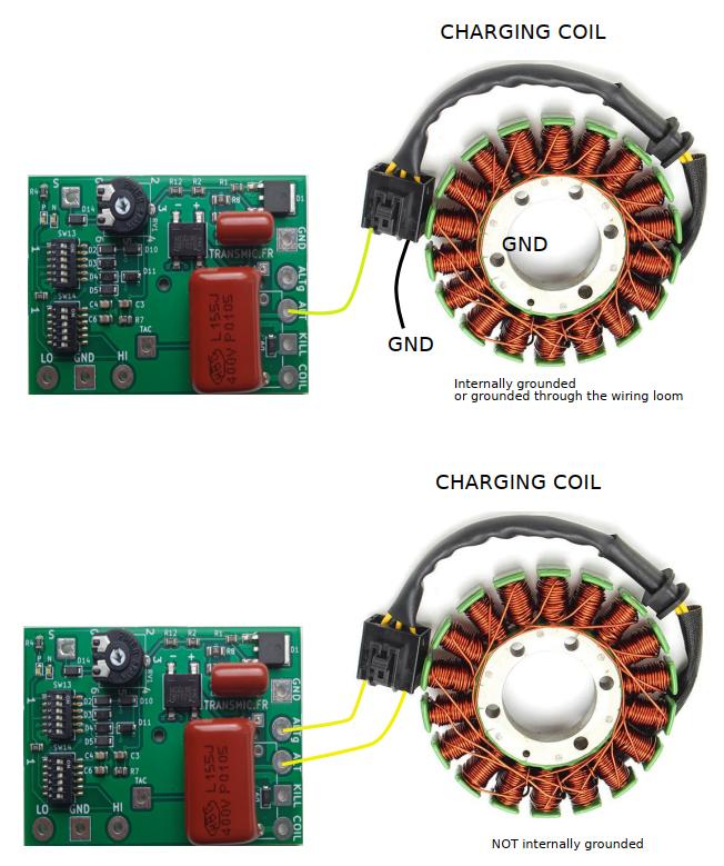
SW13-6 DIP ON: Less voltage.
SW13-6 DIP OFF: More voltage (default).
LED
LEDs have “N” and “P” labels.
They turn on when the CDI receive a Negative or Positive pulse on HI input.
TACHOMETER
A tacho output “TAC” is available. The output voltage is +12v (even if no battery or 6v battery)
Notice that it’s not a pure square signal.
Connect a tachometer that does NOT need a 50% square signal (50% off, 50% on)
IGNITION COILS
Example of suitable capacitive ignition coil rated at least for 500cc here and there.
TROUBLESHOOTING
You will need a DC voltmeter. The best is an old “Analog Needle meter”.
Step 1
Download troubleshoot step1
– Don’t connect any pickup.
– Don’t connect the Kill Switch or any Safety switch.
– Connect the GND plug of the CDI to the ground (minus battery or motorcycle frame)
– Connect the ignition coil to the COIL output of the CDI.
– Remove the sparkplug from the engine and connect the metal body to a GOOD metal frame (an unpainted bolt).
– Connect a DC voltmeter between GND(ground) and KILL pad.
– If the stator/charging coil IS NOT internally connected to ground, it has 2 wires:
– Connect any of them to ALT and the other to ALTg input of the CDI.
– DIP Switch SW13-6 can be ON for full rectification or OFF for half rectification (Don’t hesitate to test both position).
– If the stator (charging coil) IS internally connected to ground, (One wire is already internally connected to ground):
– Connect the only output wire of the charging coil to ALT input of the CDI.
– DIP Switch SW13-6 has no effect. (can be on or off).
Other DIP switches positions don’t matter for step 1.
Then:
– Electric start or spin the engine with a drill or Kick start a few times to load the capacitor.
The voltmeter should raise up to 100 or 200Vdc then quickly decrease.
(Due to the capacitor discharging into the CDI and the voltmeter).
If not: Check grounds, connections, joints, charging coil (stator), change switch 6 position.
Step 2
Download troubleshoot step2
– Same connections as Step 1 (Still no pickup, no kill nor Safety switches connected.)
– Turn SW13 DIP Switches positions 1, 3, 5 to ON.
– Turn RV1 to the minimum resistance (Position: 0).
– Kick start or electric start a few times to load the capacitor.
– Once the main big capacitor C1 is charged and the voltmeter shows 100 to 200Vdc, then in the same second:
– Connect the + 12v battery to HI input:
– Labeled “P” Led turns on.
– The big Capacitor discharge into the ignition coil and one spark must fire at the sparkplug.
If not: Check grounds, connections, joints, SCR, ignition coil, spark plug cables, spark plug.
Redo this Step 2 but this time connect the +12v battery to the LO input. (Led won’t light.)
Step 3
Download troubleshoot step3
– Same connections as Step 1 ( Still no pickup, no kill nor Safety switches)
– Turn SW13 DIP Switches positions 2, 3, 4, 5 to ON.
– Turn RV1 to the minimum resistance (Position: 0).
– Connect the pickup coil between a GOOD metal frame (ground) and HI input of the CDI.
– Kick start or electric start to load the capacitor and send trigger pulses:
– The main capacitor C1 is charged and the voltmeter should read 100 to 200Vdc.
– At the same time, when the piston approaches the TDC and passes in front of the pickup, a pulse is produce by the pickup:
– LED blinks. (P or N or both leds according to the type of pickup)
– The pickup pulse then trigger the SCR and the big capacitor C1 discharges into the ignition coil, a spark must fire at the sparkplug.
If not: Check grounds, connections, joints, pickup coil, RV1 is set at 0, reverse the 2 wires of the pickup coil.
VIDEOS.
Suzuki GN400 with ACCDIv27+
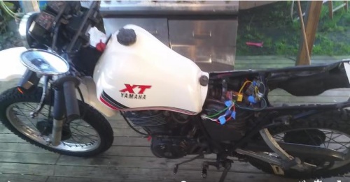
Marty bought a 1984 wrecked XT600 without ignition and harness wiring.
Got it running again even if it seems like he has some carbs works to do…
Analog CDI v2.4 on a XT400:
3 Analog CDI v2.6 on an outboard Suzuki DT30C (3cyl 2stk)
Analog CDI v2.4 on a XT125/1982:
Pickup polarity (PN or NP):
Analog CDI v2.4 at 15,000rpm:
CDI diagnosis and explanation:
Sw14 switch n1 ON reduction igniction to TM11-03 ?
For KTM and SEM ignition please post your comment in the right page: https://transmic.fr/2016/07/03/ac-cdi-ktm-sem/
Setting for TM11-03 has been corrected ans described there.
Hi
Does this CDI support 1990 Honda cr250
Mine has been stolen and I couldn’t find any alternatives that fit
And the only available cdi boxs for this model are in Ebay and they are extremely expensive even though they are in a nasty condition
If this model fits my dirt bike I will buy it
Hi,
I don’t have any direct feedbacks on Honda CR250. Nevertheless looking at some info I gathered on www, It should be OK:
Honda CR250 – 1900 is a KZ3 model
– Only one external pickup.
– Only one metal tab on the flywheel that seems to triggers at 10° btdc
– A charging coil into the stator.
– A CDI Box for CR250R (1989-1996) OEM 30410-KZ3-004
Parts list: https://www.bike-parts.fr/honda-moto/250-MOTO/CR/1990/CR250RL/Moteur/ALTERNATEUR–CARTER-MOTEUR-GAUCHE–BOITIER-CDI/13KZ3L41/E__0600/1/4291
I didn’t find a wiring diagram of the bike. Do you have one?
You will also have to check if the pickup is still Negative then Positive (like Honda’s)
A simple oscilloscope trace will tell. An Android phone + 2 resistors can make a scope.
As a 2 stroke engine, you’ll have to set SW14-1 and SW14-2 (https://transmic.fr/wp-content/uploads/2021/10/2stk_timing.jpg)
Добрый день!
Подойдет ли Ваша схема к мотору Hirth f33 ? Там CDI использует 3 провода,
1) вход с высоковольтной катушки генератора
2) масса
3 ) выход на катушку зажигания
Me too but how do you find out if it will work on a 2 cylinder cm400a hondamatic 4 stroke motorcycle that’s the one I need ..
Hi
Thank you for your reply
Yes it still NP pickup coil
I have pictures of the oscilloscope and I have the wiring diagram
How can I send them to you
Thank you so much
you can PM me with the “Contact” link on the top of the page or frtransmic@gmail.com
This snapshot of the Honda CR250 pickup is perfect. We do see it’s NP and the wiring diagram shows a simple ACCDI too.
I don’t see why ACCDI v27 wouldn’t work as it can use Negative pulse and timing for 2 strokes. Setting should be:
SW13-1,2,5 = ON
SW14-1,2 (on or off)
SW14-3,4,5 = ON
Thank you for your reply brother
I replied into your mail
Again thanks my dear
There is about 3-4 hundred of us 1979-1982 cm400a hondamatic 1984 450 handamatic that all need a replacement cdi box they are rare and it would be great if you built one for us that would work we could use our own wires from the old one and just solder them onto your same board it would be a real good thing .
Please help us.. we have all the wires and connectors from our old dead CDI modules Nippondenso Part Number 070000-0550 I would buy 2 of them like everybody else that has the same problem and the same bikes mine is the 1979 CM400A hondamatic it’s a great bike just no spark and I really want to put a new CDI made by you people into my bike
The 1979 nippondenso 070000-0550 cdi has 11 wires on it all color coded it’s a small cdi board but they sealed it into epoxy about 4 decades ago and it’s real hard to get apart I was able to get mine apart without breaking the circuit board but the component side is still encased in epoxy and it is just almost impossible to get it off I tried everything . But you seem to make a way better CDI so I would rather get a brand new aftermarket CDI from your company like the other people in the group All I want for Christmass is for somebody to build this CDI
Wow that CDI you build is a beautiful looking thing i have been searching everywhere for people like you that actually can build such a Beauty of a thing ..I just thought I would mention that to you . I bet you it wouldn’t be that hard for somebody like you guys to just make a couple additional changes to this CDI you built and it could probably be made to work just fine .. I am just saying . Anyways merry Christmass and all that jazz keep on biking and keep up the good work …
Hello,
Thanks for your kind words. Are you sure it’s the CDI? you’ve crossed everything else? kill sw, sparkplug, cap, charging coil, pickup… Well it’s a 40years old electronic, no surprise it’s dead!
From what I saw on Youtube there is only one magnet on the rotor and only one pickup. Since Honda CM400,CB400 are 360° crankshaft engine, I’m sure it’s a wasted spark system, that mean only one ACCDI v27 could be used. (Or ACCDI v10 is you want better performance)
I don’t have the bike at hand obviously, so you’ll have to do some test to find which wire is which.
Follow up on PM if needed. Contact on top and bottom of the page
Do you have a pdf for 2 pickup compatibility? Both links download 1 pickup pdf.
Corrected !
Hi,
Have a 98 Skidoo Mach 1 with rotax 3 cylinder 2 stroke. This has an immobilizer and is a one year only cdi. No longer available. Its a pretty high output 134hp 10k rpm 2 stroke.
The 120 degree seperation 3 cylinder fires wasted spark on all three cylinders everytime one of the 3 triggers are passed by the pickup coil.
Your instructions say your boxes will not work with one pickup and multiple coils but I think 3 of your cdi’s would work fine in this engine, yes?
If so since I have to buy 3, which woukd you recommend or perhaps its best to modify yours on a new circuit?
Hi,
As per your description, yes 3 cdi would work. (This Suzuki 3cyl outboard runs on 3CDI)
The pickup coil will trigger all of them at the same time (wasted spark) and charging coil will charge all 3.
BTW if this is the same wiring as yours, there are 2 charging coils, that must be figured out (why and how to wire them?)
https://www.dootalk.com/attachments/wiring-png.1254065/
Also you’ll have to know what the pickup polarity is. (PN or NP) Even though wires can be swapped…
If you consider ordering, contact me prior to order
Bonjour,
Bravo pour votre site et votre travail sur les CDI qui permet de sauver certaines machines !
Dans le cas d’une moto avec un seul capteur comme mon Yam DTMX125, y a-t-il un avantage à utiliser la version 2.7 par rapport aux versions plus anciennes ?
Et est-ce que le potentiomètre a une utilité dans ce cas puisqu’il n’y a pas de saut à régler entre deux capteurs ?
cordialement
Bonjour,
La question ne se pose plus vu qu’il n’y a plus d’anciens modeles.
>puisqu’il n’y a pas de saut à régler entre deux capteurs ?
Non. le potentiomètre gére le saut entre les 2 impulsions du même capteur lorsque “l’aimant” du stator arrive puis quitte le pickup.
Merci pour votre réponse.
Si je comprends bien, dans le cas d’un seul capteur, l’impulsion négative est aussi utilisée après redressement ?
oui en quelque sorte, c’est ca.
Hi Thierri,
I have my ACCDI v2.7+ and have been working-out how to wire it for my SRX600. I think I understand now but there looks like an error on your XT600 wiring diagram – the charging coil wires (Red and Brown) are shown going to the ACCDI ALT and GND connections when you text suggests it is ALT and ALTg (?) – that had me confused!
Anyway, I hope I understand correctly and look forward to getting it working. Thanks for all your good work.
Hi Tim,
Reload the wiring diagram, I’ve changed it. On recent ACCDI2.7 it’s now ALT and ALTg.
(ALTg can be connected either to gnd or to full rectification with SW13-6)
Cheers
Hi Thierry, I bought an AC CDI V2.7+. I would like to know what type of pick up I should use for this CDI and if possible a reference to be able to buy it. I am going to put this CDI in a single-cylinder SANGLAS 400, at start it must have 0º so that it does not recoil, since a pedal starts, once it starts the advance is at 7º and at maximum revolutions it reaches 35º of advance. I congratulate you for your page and the information of these ignitions. Thanks and regards
Hi and thank you Francisco,
ACCDI v27 uses an ANALOG pickup (aka “pickup coil” or VR that stands for “Variable Reluctor”)
i.e This one: https://www.aliexpress.com/item/4000013985407.html
>it must have 0º so that it does not recoil, since a pedal starts, once it starts the advance is at 7º and at maximum revolutions it reaches 35º of advance
No. You should understand that ADVANCE IS NOT ADJUSTABLE with ACCDI v27!
Advance values come from the lenght of the magnet on the flywheel, and for less part form the CDI settings and a little bit from the pickup.
If you want to tune and fine adjust the advance you need a programmable CDI (like ACCDI v11)
Hello Thierry!
I’m looking around the shop right now to buy a CDI unit. However, I can’t get any further at some points.
I own a Yamaha TT600S 4GV (1993) and according to your FAQ (https://transmic.fr/2016/07/02/faq/) it should have a DCCDI. On the other hand, it has no battery, and the XT600 models that have the same CDI unit are listed with you under ACCDI.
Can you help me choose the right one? The original part number is: (Yamaha) 3YP-00 070000-2180 QAC18.
Thank you in advance and best regards!
Hello Tobias,
Right TT600 and XT600 share the same ACCDI.
The typo into the FAQ page has been corrected. Thanks for spotting it!
For this TT600 you can choose ACCDIv27+ or ACCDIv11 depending on what you want to do and to spend…
BR
I have an XT550 that has a bad pickup coil. Can this CDI to be used to run the bike off of the other pickup coil that’s still good? (For example, running based off of the 12 degree coil at all times)
Yes but..
With ACCDIv2.7: Engine will knock at idle if running based of the 36° or no power at high revs when based of the 12° coil.
With ACCDIv11: Engine run OK based of the 36° or no power at high revs when based of the 12° coil.
Hello,
I’m planning on upgrading ignition system on my 1982 Suzuki GN400. Which kind of ignition coil would you recommend, along with ACCDI v2.7+? Also, I think there’s a mistake in settings pdf, as sw13-3 is mentioned both on and off.
Thanks
Hi, I don’t recommend any. There are 2 links toward compatible coils above.
No mistake. Try both and keep the setting that work best on your bike.
Hi
Question on switch setting for GN400/SP400 Suzuki
SW13 position 3 is marked as on and off? also no mention of position 4 what should that be set at>
SW14 no mention of position 6 what should that be?
Also can you run the V2.7 plus model on a less that 350 cc if need to?
Thanks
Hi,
Documentation updated !
https://transmic.fr/wp-content/ACCDIv25/v27_modeles_et_switch_2pkp.pdf
Yes v27+ can run on any cc.
Can Confirm fit for 1986 Atc125m.. still dialing in the advance . The production #s were super low on this machine and I was out of options.. couldn’t locate a replacement.. this lil box is awesome. I can share pictures of the wiring and the DP switch settings if anyone needs. Thanks again
ac-cdi-v2.7? It was 2.6 when I started this email?
I am working on a 1980 85 Suzuki DR400 4stroke single trail bike that the Net tells should have a 6volt system.
DC provides power for lights (not needed for trail work) one wire.
Ac provides power for spark. Three wires
It has two spaced (ac I believe) pickup units mounted at either end of a bracket triggered by the one magnet protruding through the flywheel.
Although the flywheel has magnets imbedded around its inner surface to excite an dc coil and its opposing ac coil.
Your ac-cdi is just what I am looking for. The little DIY involvement suits me.
How much to get it to New Zealand?
ACCDI v27 doesn’t need DC power so 6 or 12v doesn’t matter.
AFAIK DR400 and GN400 share the same engine.
The stator of GN400 looks like this.
Connection to CDI is described above.
For shipping to NZ just order it, you’ll see the price before to pay.
Hello
I have model boat engines I need a DC CDI ignition programmable. I need it to do 20,000rpm to 25,000RPM what ignition do you recommend?
Thank answer
https://transmic.fr/2019/08/21/dc-cdi-v7/#comments
do you post to Australia and if so how long does it take approximately and how much does it cost
No problem. Australia and NZ are the longest, around 4weeks. Price depends on what option you choose…Around 7€.
You can add the item to your basket, shipping price will be displayed before you have to pay, then cancel the buy.
Just purchased a ACCDI v2.7 to use on a XT600 super tenere
Regarding DIP switch 13 is switch 6 on or off ?
Both work. But SW13-6 ON is like the genuine part.
Hello,
Can you tell me if your ac-cdi 2.7 is compatible with a Honda TLM 250 trial bike.
It’s a 2-stroke engine without battery:
1 pulse generator
primary coil resistance: 0.3 Ohms
secondary coil resistance: 6.3 Ohms
Ignition timing: 19° BTDC/2000 rpm
thank you
Hello Eric,
L’inconnu est le timing du pickup: Pour obtenir 19° BTDC/2000 rpm, il faut que le pickup soit fixé a 19° MINIMUM.
S’il est a 19-20°, l’accdiv27 marchera bien. Ne reste qu’a connaitre la polarité du pickup. (voir ci-dessus)
Certains constructeurs comme Yam décalent le pickup vers 70° et le CDI attend le temps nécessaire avant d’envoyer étincelle. Dans ce cas il faut un ACCDI programmable comme mon v12
Mais ce n’est généralement pas le cas chez Honda.
Pour en etre certain, faut mesurer selon l’annexe 1 du doc: https://transmic.fr/wp-content/ACCDIv12/Setup_IgnitionBox_ACv12r4c1.pdf
Bonjour Thierry,
Je trouve un angle de 45° pour le positionnement du pickup sur la Honda TLM.
Je vais donc te commander un CDI.
Cordialement
Eric
Bonjour Thierry,
En attendant la livraison de mon CDI, j’ai poursuivi les recherches.
Pour information mon Pickup est de type PN
Cordialement
Eric
Merci pour l’info.
An attendant vous pouvez deja reflechir a la position des switchs en partant de la config des autres moteurs en PN:
https://transmic.fr/wp-content/ACCDIv25/v27_modeles_et_switch_1pkp.pdf
Cdt
Hi,
I recently purchased a 1987 Husqvarna TE510 with no spark. I checked the Stator and found it to be out of range. so a purchased a new after market stator. Still no spark. I then checked the coil/cdi and found it was also out of range. No resistance reading on black to red as outlined in your documentation. I tried to install and generic CDI and this created a pretty bad kick back on ever kick. I believe this issue lies in the generic aftermarket cdi. Would your cdi work on this bike? Thank you.
Hi,
Yes the generic aftermarket cdi has a bad timing. Sparks too soon.
Use my ACCDIv27+ instead with 4 strokes settings like TM14-05
Hi,
I have a Kim lc4 640 I am using your ignition on. It is difficult to work out the static timing for the ignition pickup, which is fixed, I think it is about 64 deg BTDC but if there is anyone who could confirm or correct this it would be helpful. Thank you.
KTM LC4 640 1999 has a 38° BTDC timing advance at 6000rpm.
Hi,
Will this cdi work in Yamaha RD125LC 1986. No need for YPVS.
It has one pulse per revolution and stock cdi has 3 wires from magneto AC supply.
Hi,
Yes it should.
it seems that the stator has 1 low and 1 high speed coil. You should be able to use both coils in serial or just the HS coil.
HV coil produces 70 odd volts AC at kick speed.
Please try to confirm the timing by measuring the length of the bar on the flywheel: https://transmic.fr/2021/09/23/read-timing-from-flywheel/