AC-CDI v11 is End Of Live and has been replaced by AC-CDI v12
This technology will make your motorcycle tuning much simpler and faster.
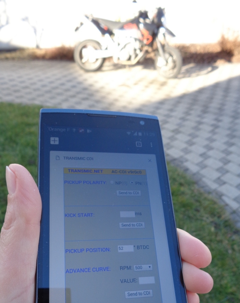
Just connect your phone to your motorcycle and you’re ready to go!
A programmable ignition is extremely valuable in repair work as it fits a wide range of bikes.
It’s especially useful if the original part has been discontinued or is overpriced.
And of course it’s a must-have if you are wishing to tune the engine.
Features
- Programmable AC-CDI
- Suitable for ONE or TWO* cylinders
- For [2 strokes engines] and for [4 strokes engines with wasted spark*]
* On 4stk engines with a pickup on the crankshaft, one spark occurs during the compression stroke and another during the exhaust stroke.
- Easy programming via WiFi connection.
- You need a simple web browser on any smartphone or laptop. (No app)
- One programmable ignition timing curve.
- 80MHz MicroController control unit.
- Rev from 10 to 20,000 RPM.
- 0 deg advance from 1 to 500 RPM. (To avoid kickback)
- Adjustable timing in 13 steps from 500 to 20,000RPM.
- Hard rev limiter.
- Legal Temporary rev limiter.
- Live Display of RPM and Timing via Wifi.
- 2 inputs for an inductive pickup (VR).
- VR conditioner to extract pickup signal in noisy environment.
- 1 input for Digital sensors (Hall, Optical sensors).
- 1 output for a Capacitive coil type.
- Stator can be half or full rectified. (For more power and ground isolation)
- Non volatile configuration.
- 12v Tachometer signal.
- 300V 8A 12pins connector.
- Kill switch input.
- Power supply voltage DC 6 to 18 volts (For Setup AND to operate).
- Current drain: 30mA – 100mA.
- Protected against reverse supply voltage.
- Dimensions: 100 x 60 x 25mm (3.9 x 2.4 x 1inch)
- Plastic box potted for Electrical insulation, Protecting components from mechanical shock and vibration, thermal shock or Moisture.
- Made in France.
Cylinders
* Twin-cylinders at 360° crankshaft angle:
The engine works with WASTED spark.
If there is ONE twin coil:
=> This AC-CDI works.
See: CDI compatibility
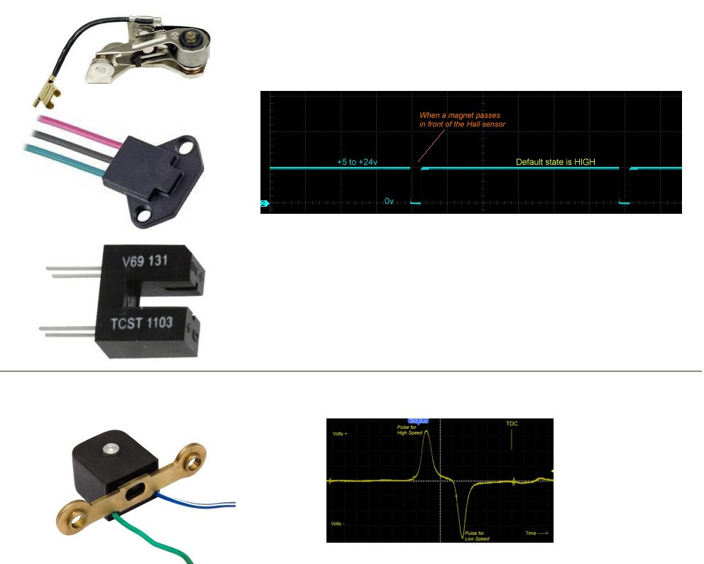
Pickup
It’s made of a coil of wire wrapped around a magnet.
When a ferrous part passes by the magnet, the magnetic field is modified and a voltage pulse is created in the coil generating a sine wave.
ACCDIv11 has:
– 1 input for inductive pickup (VR/pickup coil) with 1 signal per crank revolution. (Pickup must puts out 3 to 100Vac)
– 1 input for Digital sensor (Hall Effect Sensor, Optical sensors even breakerpoints).
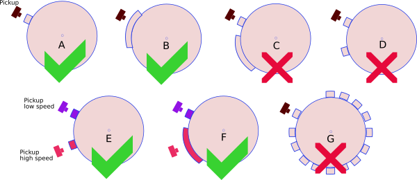
– This CDI works with 1 reluctor (The metal stripe on the flywheel).
– This CDI DOES NOT work with multi-pulse pickup (ie 2 reluctors on flywheel).
– This CDI DOES NOT work with a missing tooth flywheel.
Pickup Polarity
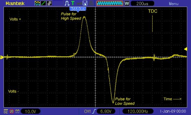
When the bar/magnet on the stator passes in front of the pickup, the pickup generates two pulses of OPPOSITE polarity.
A pickup has 2 wires. If you ground wire number 1, wire number 2 will put out a Positive pulse first when the rising edge comes, then a Negative pulse when the falling edge leaves. I call it PN.
If you ground wire number 2, wire number 1 will put out a Negative pulse first, then a Positive pulse. I call it NP.
Pickup Polarity MUST be Positive then Negative. to work with this CDI.
Check the polarity of the pickup (Negative going then Positive/(I call it NP) or the opposite PN: Positive going then Negative) with a Needle galvanometer (in milliAmp position) while kicking.
If the polarity is Negative then Positive(NP) then the leads are backward, just swap the wires to change the pickup polarity !
Watchout! If the pickup is internaly grounded and output ONLY one wire, you won’t be able to change the polarity.
So if the polarity is NP (Negative first) then you CANNOT use this ignition!
Pickup Position
“Pickup Position” is the number of degrees between the very first pulse from the pickup and TDC
To be able to provide the largest advance timing (Example 36° @ 4500rpm) the pickup MUST send a trigger signal BEFORE the piston reaches 36° before top dead center (BTDC).
The “Pickup Position” on the Yam XT600 is 50°. Many Yamahas have a “Pickup Position” of 72 degrees.
This “Pickup Position” is dependent on:
– Where the pickup is mechanically located with respect to TDC?
– Where is the flywheel’s bar located?
– How long is the flywheel’s bar?
“Pickup Position” AKA “Max Advance” = “Base Advance” + “Flywheel’s bar Length”
“Base Advance” value sometime appears is User Manuel.
Length of the flywheel’s bar can be measured this way.
You may measure the “Pickup Position” using a protractor.
or with a caliper and some math.
Temporary Legal Rev Limiter
After 30 seconds, Kill switch will acts normally and stop the CDI.
After the bike has been stopped and restarted by the Master Ignition Key, the CDI runs without restriction.
In countries where 50cc are strictly restricted, the bike seems legal in case of control…
It can also be handy if a beginner rider tries the bike.
Live Display of RPM vs Timing via Wifi
For diagnostic or tuning purpose, it’s possible to live view RPM and Timing in degrees BTDC on a remote PC connected through Wifi: Video
Because of the impact on CDI performance, please disable this function when you are done!
Ignition timing
– Draw the ignition timing curve into this XLS sheet.
Rev Limiter
The last RPM value that has been entered is the “rev limit” that stop all sparks.
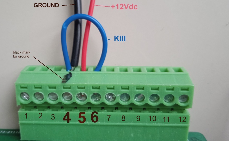
How to Wire
12 pins Connector
For Half-Rectification and Common ground.
For Full-Rectification and Isolated ground. (More power)
HowTo wire ACCDIv11 on XT550-600
HowTo setup
To program the ignition, please Print and follow this procedure: Setup Ignition box.pdf
The 12pins connector has a marker trace on pin4 which is Ground.
1) Connect a Black wire from pin4 to black plug of a 12v battery.
2) Wire a bridge between ground-pin4 and kill-pin6.
3) Connect a Red wire to +12v pin5 only.
Don’t mix them up !
4) Connect the Red wire to the red plug of the battery.
5) Led blinks 3times while a WiFi Access Point named “Transmic_ign” show up on you laptop/smartphone.
Diagnose with LED.
As soon as a pickup signal is detected, led blinks in rhythm.
If the Maximum RPM is reached, the led turns off. If minimum RPM is reached, led turns off.
– If the box starts in SETUP Mode : Led blinks 3 times before flashing once every 5 seconds.
When data arrives via WIFI, led briefly flashes.
PHOTOS.
Transmic CDI vs Honda CDI ? Dyno speak volume:
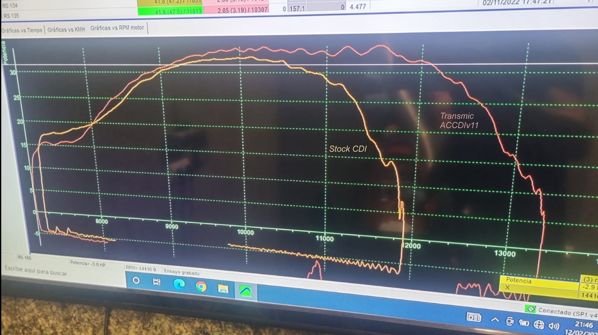
Honda NSR125 with Malossi 180cc, Tyga exhaust, Italkit reeds tuned by “Cuco Racing Team – Spain”
VIDEOS
Various parameters must be memorized beforehand
I recommend to roughly determine the position of the sensor with a graduated disc
The stator must be labeled for a pre-adjustment with 10,20,30° marks
First try with a car battery
The positive pulse from the pickup must come first, otherwise swap the cables, otherwise the timing will be clearly wrong
So not this way !
The engine runs under 6v under its own power supply
5 degrees offset
Offset corrected
Will it go with the Vape too?
Safe settings: pickup position:70/pickup type:0/adv 0-500:0/5@1000/5@2000/10@3000/20@4000/30@6000
VERSIONS
- Version v11r0c0:
- POC.
- Version v11r4c0:
- First commercial version.
- Version v11r5c0:
- [soft] Firmware improvement.
- Version v11r5c1:
- [soft] Wifi Console mode added.
- [soft] Legal Rev Limiter can be disabled.
- [soft] Max pickup position is now 180°.
- [soft] Add Hall Effect Sensor compatibility.
- [hard] Add Input for a Hall Effect Sensor.
- [hard] Add Input for a 2nd analog pickup.
- Version v11r5c3:
- [soft] Pickup diagnostic feature added.
- Version v11r6c3:
- [soft] Led blinks slower.
- [soft] Fix bug for XT600.
- [soft] Changes in HTML Form.
- [soft] Add a “Factory Restore” button.
great job congratulations! I wanted to ask you, in your opinion is it possible that it works on a vespa 50 (pk 50 s) with electronic ignition? In this case I’m talking about the original Ducati 4-pole ignition with pick-up on the stator. In case I can send you some photos or you can find them on the internet! Thanks and Merry Christmas!
Thanks!
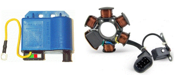
Is it this one ?
If it has one external pickup, only one bar on the flywheel and a +12v battery: Yes it works.
You just have to be sure that the pickup puts out a positive pulse first otherwise you’ll have to invert the 2 wires that go the pkp.
(Read Pickup polarity section in this page)
Regards
Hello! I only saw the message now! Then the stator (4 poles) has the internal pickup and the external HV coil. is the model without battery!
https://www.vesparesources.com/uploads/monthly_2017_10/59e8913d20b4a_Schermata2017-10-19alle13_48_50.png.cb30d83fcfca90e9a2d12b8bc12423e4.png
Thanks for the Answer! I want the V11 so bad but from the text I took it that it sadly won’t work with 2 pick-ups, right?
After reading the text more thoroughly, I think that two pickups should work, but I’m not sure where I can connect the second one, just to the same port as the first? (That can’t be right, can it? )
Or do I not need two pickups at all with the programmable ignition curve and one is enough? (sorry for the spam)
You took it right. ACCDIv11 DID NOT used 2 pickups.
In fact it didn’t need the LOW pickup that sends a pulse at 12°btdc
The cdi uses the HIGH rpm pickup at 36° to make 12° from it.
I’m currently testing a new version of ACCDIv11r5c1 with added features (See https://transmic.fr/2021/08/14/ac-cdi-v11/#versions )
This version now uses the two pickups on XT550-600 but I haven’t got the time to write the documentation…
Thank you so much!
I think I’m slowly getting there.
now I ask myself only the question with the wiring. I have the circuit diagram from am motorcycle, sind from the pickups come 3 cables: 12°, 36° and the pickup ground. Is said ground important or is it simply ignored?
and what exactly is the HV cable in your wiring scheme? a brown and a red cable come out of my alternator, where do i connect them? 🙂
Oh i see now your updatet wiring, thanks! going to purchase 😀
I have purchased this excellent product for older 4-stroke motorcycles, programmable curve between 0 degrees and 38 degrees. Thank you for your help and knowledge on these products.
Ciao Thierry, do you have any experience using your CDI on a points Piaggio Ciao / Bravo ?
Hi,
No. But there is not improvement in performance to expect on a 50cc…
ahahah…you are right but i m interested more in reliability than in performance !
I think that the most reliable assembly is a TCI with a Hall sensor so there is no use of the alternator neither the pickup coil, but it needs a battery and it’s a big mod !
Hello,
Looking for a cdi for Artic Cat spirit 500 2cyl 2 stroke. Have your accdi 2.7+ and have had the motor running but not well. nipponddenso 070000-0680 is factory unit cdi. Can you help out..
Hello,
You mean the Artic Cat snowmobile with the “Spirit” engine from Suzuki?
It seems to be a 360° parallel twin (both pistons up and down simultanously)
Beside it runs with the ACCDIv27+ so I bet there is only ONE pickup and a twin ignition coil to fire both cyl. at the same time.
Sure the ACCDIv27 is a crude ignition created as an affordable solution.
If you want to fine tune the advance timing, the ACCDIv11 is better (or a TCIv11 but the ignition coil MUST be replaced)
To set the v11 you MUST know the pickup position BTDC, don’t ask me 🙂
I described same ways to do it on both web pages.
Th
bonjour Thierry,
je suis motivé pour prendre la v11 pour ma xt 600 3TBK.
Petite question suite à la lecture de tes commentaires et quelques recherches :
la version ACCDIv11r5c1 permettrait d’utiliser les 2 capteurs (12° et 36°) si je vous comprends bien.
par contre il y’a une mofif Hardware dans la ACCDIv11r5c1 pour une deuxième entre analogique pour le capteur 12° donc.
La version actuellement en vente serait compatible ou dois-je attendre encore ?
Encore merci pour ton travail
Bonjour et merci pour votre commande.
La version a ce jour est ACCDIv11r6c1 donc elle integre de r5c1 une entrée pour le pickup low a 12° dans le cas des XT600.
merci pour votre réponse.
Colis réceptionné ce jour, merci !!
Déjà connecté dessus j’ai un petit doute quand à la valeur du PICKUP
(oui mon anglais est …. fatigué.. et malgré google traduction je ne suis pas sur de comprendre)
en fait ces deux phrases me mette le doute :
“The “Pickup Position” on the Yam XT600 is 50°”
“The cdi uses the HIGH rpm pickup at 36°”
pourquoi 50° , on a un capteur 12° et un autre 36°
pouvez-vous svp me confirmer pour un 600XT:
PICKUP TYPE : 0 (vr analog)
PICKUP POSITION : 36 (BTDC)
aussi dans la documentation il n’y pas d’indication concernant SHAFT: Crankshaft ou CamShaft
je suppose que c’est pour ceux qui on le capteur sur le haut moteur ?
je laisse donc Crankshaft pour mon utilisation.
Encore merci,
hâte de tester sur la moto !!
Le pickup de la Yamaha XT600 est physiquement placé à 50°.
Le CDI attend un peu puis envoi l’étincelle à 36° BTDC.
Les pickups sont TOUJOURS positionnés a une valeur SUPÉRIEURE à la valeur d’avance maximale.
(pour obtenir 36° d’avance max, les ingénieurs Yam auraient pu placer mécaniquement le capteur a 37, 50, 70, 93° btdc etc, le CDI se débrouille mais il faut le lui dire.)
PICKUP TYPE : 0 (vr analog)
PICKUP POSITION : 50 (BTDC)
>je suppose que c’est pour ceux qui on le capteur sur le haut moteur ?
>je laisse donc Crankshaft pour mon utilisation.
Evidemment.
Merci pour votre réponse plus que complète !
Demain ça démarre du coup, j’ai hâte !
Bonjour ,
Je viens donner nouvelles,
j’ai enfin eu le temps de monter le CDI sur ma moto.
Malheureusement après de bonnes heures de recherche je sèche -> pas d’étincelles.
1) j’ai mesuré à l’oscilloscope je pense l’essentiel des composants (je peux faire des captures si besoin ?)
– vérif de la tension HT du stator : OK (sinus de -150v à +150v environ)
– vérif du capteur PICKUP : OK (premier pic positif d’environ 7v suivi du négatif à -7v)
2) j’ai enlever le faisceau elec de la moto et fait un faisceau sur mesure pour uniquement cabler le CDI tel que sur le schema “full rectification” (avec un inter pour le “kill switch” pour accéder au paramétrage facilement)
– je n’ai pas essayé en Half-rectification par contre.. mais je ne verrais pas pourquoi ce serait mieux
3) batterie neuve chargé ou alimentation de labo pour le 12v (avec test de masse différentes pour être sur , cadre, moteur, sur le régul, etc..)
4) bougie neuve, bobine neuve, antiparasite neuf (même si à l’ohmètre tout était bon mais j’avais ça en stock donc autant essayer)
-> les symptôme sont :
– sur la broche 1 (sortie CDI pour bobine) il n’y a rien : mesuré à l’oscillo. (bobine branchée ou non branchée)
– la led du boitier clignote si je fais tourner le démarreur ou un coup de kick (je suppose donc qu’il capte bien le PICKUP)
– j’ai mis une courbe d’avance simple à 3 points (500-8 ; 1000-10 ; 6000-30 ) , si je fais “READ” c’est bien écrit comme dans la doc.
Voilà, je vous avoue que je sèche . ça fait beaucoup à lire mais je tenais à essayer d’être le plus précis possible. Avez-vous une idée ou une piste ? je peux bien évidemment mesurer ou fournir d’autre informations si nécessaires
En vous remerciant par avance,
Robin
>la led du boitier clignote si je fais tourner le démarreur
Donc le CDI voit bien le pickup
>sur la broche 1 (sortie CDI pour bobine) il n’y a rien
C’est qu’il manque la Haute Tension
Essayez en Half rectification. J’ai vu des cas ou ca ne marchait pas en full. Surement a cause de masse non communes…
Th
Si besoin joignez moi directement par PM (mon adresse est en haut a dr. “Contact Me”)
Après des heures de recherches le résultat est tombé : STATOR HS .
Encore merci pour les nombreux conseils et pour l’aide apporté.
A bientôt j’espère et bonne continuation !