This DC-CDI is EOL (End Of Live = no more parts, support, update)
Consider to build DC-CDI v7 instead
Adaptation done by: 
Characteristics
- Same software as AC-CDI v7
- For single cyl.
- 1 advance curve.
- No alternator.
DOWNLOAD
| PIC 16F628A | v2.1 | ||||
|---|---|---|---|---|---|
| DC-CDI | Schematic | PCB | Board layout | Partlist | Eagle files |
How does it works?
Software is the same as AC-CDI version 7
Only the Hardware is different: High Voltage is no more coming from a charging coil, but it’s generating from the 12v battery.
A UC3845 is driving a home made transformer that raise the tension from 12Vdc to around 200Vac.
The HV is rectify by D1 and charges C9 capacitor.
Pulses coming from the 36° pickup are limited to 5 volts by D7 Zener then trigger the PIC (RB4 – pin 10).
(PIC input detect any tension higher than 1,8 Volts.)
D2 LED turns on at each pulse received from sensor 36°. (You can remove R17 and LED2 if not necessary)
A delayed pulse, according to the programmed advance curve, is available on RA2 (pin 1) and trigger the SCR T3 via LED1,R12-C14.
The pulse also stops the High Voltage through T2 and shutdown pin1 of UC3845.
The polarity of the pickup is very important, don’t hesitate to invert the 2 wires of the pickup.
SCR is BT151-500
FET is IRFZ44
(High power with shottky diodes integrated and very low internal resistance)
Diodes are fast rectifier diodes ( BR307 , UF5408 …3A-1000v)
Same bikes needs to lower R19 resistor value.
Exp: for Suzuki 125cc: R19 must be 560ohm (instead of 330k)
Transformer:
- Bobbin E 19/8/5 + Ferrite core EI19 (width:19mm height:14mm)
https://aliexpress.comYou can also use EE19 or E25 or ETD29.
The bigger the number the bigger the transformer and the stronger the spark. -
Primary : 0.6mm , 15 turns
Secondary : 0.2mm , 350-400 turns (as much as you can because it’s flyback) - Wind the primary and secondary in the same direction (clockwise or anti-clockwise BOTH)
- Leave a 0.05 to 0.8mm air gap between the 2 legs of the magnetic core.
- Try different air gap walue, it’s critical and can avoid the Transfo to saturate.
- The Transformer behavior depend on many factors: core, ferromagnetic material, shape, size, air gap, tension, frequency, duty cycle, primary coil, efficiency, temperature, etc etc
- It’s normal to face overheating and spikes when dealing with high currents and high voltages !
- Do not operate without ignition coil (CDI Need a load on output cause it’s a boost converter)
Frequency:
- R4, C7 are used to setup the oscillor frequency.
- Fosc = 1.72 /( R * C ) = 1.72 /( 33k * 1nF ) = 0.50MHz = 50KHz
- Fosc is the input frequency of PWM controller and output frequency provided by PWM controller is Fosc/2 = 25KHz which used as the switching pulse of MOSFET switch.
- The frequency has a lot to do with output voltage. The ON time must be long enough to let current increase to the required level, in order to get the desired output volts.
- You may want to experiment other frequencies.
- The duty cycle of pulse is controlled by the feedback control loop. (IC1 pin2)
- The greater the duty cycle, the greater the output Voltage. Until some point…
- When FB pin is high it cause the output PWM to switch off and the MOSFET will not get triggered.
- When FB pin is low it generate output pulse of high duty cycle to the MOSFET.
Oscillator IC:
- Use a UC3843 with a Max. Duty Cycle of 100% instead of a UC3845 with max Duty= 50%
- With a UC3845 we get a max voltage of 140Vac at 12000RPM with a transfo wired with primary 12T and secondary 700T
- With a UC3843 we get a max voltage of 280Vac at 12000RPM with a transfo wired with primary 12T and secondary 180T
- If you are facing mosfet overheating, considere switching to UC3845 to lower the duty cycle.
– Thanks to Irfan Galuh Sayoga
Mosfet:
- You need to verify if the mosfet goes completely ON and OFF. Measure the voltage across the mosfet both ON and OFF and calculate the internal resistance.
- If the internal resistance in higher than the datasheet value, it mean that it doesn’t totaly turn ON (it needs 10v for a guaranteed Rds)
– Increase Gate voltage by reducing R1 value
– Decrease Drain voltage by lowering the current
(increase R6 or install a low ohm resistor in the current path) - Use R6 to read volt level across it when the mosfet is ON and when it’s OFF
- Calculate values for current when both ON and OFF.
These are good indicators of what’s going on… - Mosfet can only dissipate 2watts: Add it a big heatsink with thermal paste.
Protection:
- When CS pin3 of UC3845 goes beyond 1volt IC1 output is automatically switched off.
If Tx secondary is shorted, Q2 will drive a high current, tension at R6 will increase and pin3 will go high.
Snubber:
- D2, R2, C3 are used as a snubber to protect MOSFET transistor.
- D2 is a fast diode type(BYV26C…)
- R2 goes from 100 to 100k
- C3 goes from 2nF to 10nF
- Use a snubber calculator
- If the MOSFET is getting hot, you probably have to change the snubber value according to your Tx windings…
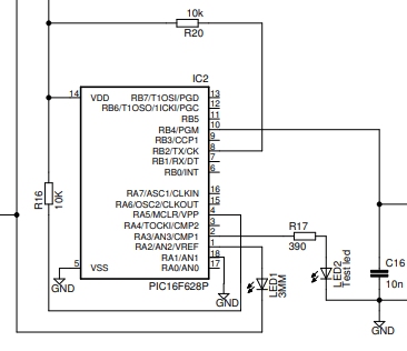
Tachometer:
[TP1]: A output is available at RB5. It can be use to drive a tachometer with the need of some other components.
The tacho output is a +5v level and 5% Duty Cycle signal.

For tachometers that need a +12v level at 50% DC signal a external processor is available here:
Duty Cycle Converter
Rev Limiter:
If RA1/pin18 is connected to ground BEFORE power up the CDI, then RPM limit setup in XLS [cell M32 of Advance_curve tab] is activated.
To deactivate the rev limiter, add a 10k pullup resistor to +5v.
DIAGNOSE with LED
– At startup, Led D2 flashes 1 to 4 times and goes off meaning that PIC .HEX software is OK.
If it doesn’t flash, something went wrong with the programming or is wrong with the power line…
– 1 time = PIC has been reset because power went below +5v.
– 2 times = PIC has been reset because +5v power went off.
– 4 times = PIC has been reset because of the RESET pin4.
– blink forever = Eeprom is empty
– When PIC input pin10 is high [>2.4v], led D2 is on. So D2 LED pulses with the pickup.
If D2 LED always stays ON, that mean either:
– pin10 is always high! => Measure pin10 and try to lower R19 to 1.8Kohm or less according to the pickup…
– or CDI is in “Autospark” mode.
Videos.
This ignition fitting a Honda SS50:
Tested with the pickup simulator:
Versionning.
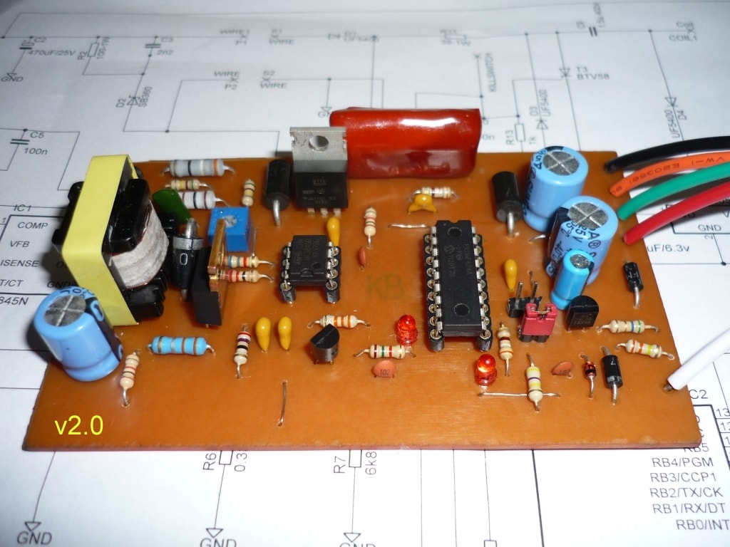
- Version 2.0:
- Initial release with a home made transformer.
- Use AC-CDI v6 software.
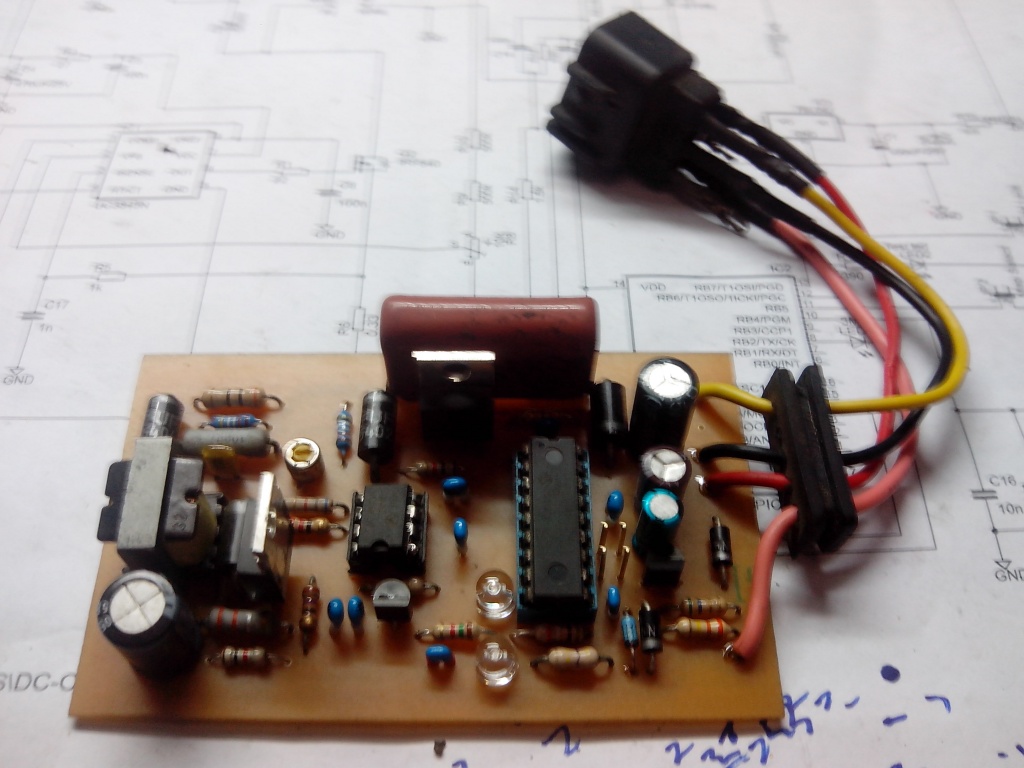
- Version 2.1:
- PCB redrawn.
- Use AC-CDI v7 software.
- Version 2.1c1:
- Improve readability of Ref on PCB.
Hi Thierry
Thanks for the fast shipping of the board for V1 .
I kind of enjoy soldering and this could be my next project , dispensing with most of the heavy flywheel sounds good . I ran my little Ducati SL2 when I first hit the road without a flywheel (just the centre to operate the points)and loved the way it picked up . Crank bearings lasted longer too !I was clocked by the police doing 82mph on their speedo as I didn’t have one ( no cameras or guns back then) not bad for a 50cc in the 1970s.
The transformer used in this unit interests me as what immediately springs to mind is a 220v-12v wall wart transformer used in reverse or perhaps a DC-DC converter ? Have you tried either of these ? Silly question but are the pcbs available because I hate etching in any shape or form .
It would be nice to dump the alternator completely and relocating a pickup is easy .
Thanks
For sure removing the inertia of a flywheel gives a more responsive engine and it’s painless for the crankshaft.
For a competion bike, it make sense but for a everyday bike how do you get the 12v power for the front light, break light, for charging the batterie etc ?
Removing the high voltage coils while keeping the low voltage ones lose the balance of the flywheel…
I first tried to use a classical wall wart 220/12v transformer in reverse mode, and it load the capacitor well ….until you fire a spark.
After being shortened by the SCR, the transformer take ages to oscillate again, due to the magnetic core remanence. Those core only work at low frequency 50Hz or so but have dysfunction at higher frq.
It would work for a lawn mower but not more.
At high frq the core as a tendancy to warm up.
In short the world of magnetic field is mysterious and building a home made transformer is really the trickiest part when building this DC-CDI !!
How can a bike run without flywheel? Please tell me i am interested. In removing flywheel of my bike to…
Mechanically: a flywheel gives the inertia needed for the engine to run steady without RPM changes and vibrations.
Vibrations can destroy other parts.
Electrically: A flywheel often/always act as a stator: magnets excite the rotor that give the High Voltage for ignition.
This HV can be build by a DC-CDI from the +12v battery
but the flywheel is also used to produce low voltage (12Vdc) for light and battery charging.
=> Without flywheel, the battery won’t be charge (you need to charge it regularly)
It also include a metal bar that trigger the pickup to give the timing for the CDI thus for the spark.
=> Without flywheel, you need to setup a pickup on another rotative part of the engine or install a lightweight flywheel just to trigger the pickup.
In one word: removing flywheel “can” be done in race conditions only (short and risky) not for everyday life…
This project was very nice, I am keen to make,but my trouble hex file for this version are the same as AC CDI v6. Where can I download it. thanks
Hi,
There is one little difference in the pinout between AC-CDI v2 (output pin8) and DC-CDI v6 (output pin9)
So you cannot use HEX from DC-CDI v6 here unless you modify the PCB of AC-CDI to use the output at pin9 (like DC-CDI)
If you want another curve than the 3 at DC-CDI contact me by PM.
Th.
The SCR used in your circuit (BTV58) is a Gate Turn Off type.
Is it used in this format in this configuration or can I substitute say for example a BT151..?
Thanks Jeff
Yes it can be substituted by a BT151-500 or more secure any SCR rated 600 to 1000volts/6-8A
There is not real need of a fast thyristor here…
my bike is twin cylinder waste spark ignition system,..my question this cdi can handle 2 ignition coil(because 2 cyl) or 1 ignition coil with 2 output (waste spark ig coil) or not?…or i must modify this circuits into 2 power.
If you engine work with wasted spark, this CDI can drive:
– ONE DUAL output ignition coil.
or
– TWO single coils in parallel but you’ll probably need to increase the capacitor value to 2uF as the charge double.
Hi
Can you please send me the components lists cause I thing m missing one or two components in my design. .
Hi
Could you please elaborate? The partlist.txt is in the web page. Which component is missing?
Preset
Ok, this is my problem, I am modifying a Aprilia 1000 RSV engine and wish to build a simple ignition system for it. Can I just use two of your units? each unit fires two coils.
We can imagine 2 CDI driving one coil each.
But you will need to check if there are 2 separate pulses coming from the pickup (49)
http://www.apriliaforum.com/forums/attachment.php?attachmentid=140386&d=1277834990
And what about injection, air/throttle/pressure/temp/knock sensors ..?
Hi
What is the value of preset present in the circuit. .
What do you mean by “preset value” ?
The position of the pickup Before Top Dead Center??
this value depend on the v6 curves
it can be 20 deg btdc for one bike, 36 for another etc etc
Hola muy lindo proyecto . Necesito una curva que tenga un avance inicial menor a la de honda s50 . Hice el DC/CDI PARA UNA YAMAHA YBR 125 . GRACIAS .
Bisa ka saya membeli cdi buatan anda.
Untuk motor 200cc DC
Sorry for write in spanish . Hi, very nice project. I need a curve that has an initial advance lower than that of honda s50. I made the DC / CDI FOR A YAMAHA YBR 125.Or can you give me a map for yamaha ybr 125 or yamaha fz 16 . THANK YOU .
Hi
no worries but use English preferably!
I can’t know the map of YOUR bike but fill in this excel file with the map you want and send it back to me using the email address on the left hand.
(there must be no error in the file or it won’t work)
how if the snubber component is not installed?.it can still working or not?
it’s a DIY transformer so we don’t know how it will behave, if it will produce lot of transient surges or not…
It will certainly work but if you want a reliable CDI it’s best to add this mosfet protection.
I think it is easy to understand,I’ll start from here,the software is simpler than your version7,thank u thiery…assalamualaikum for u
Atem, watch out! AC-CDI and DC-CDI are not the same. At first you must know what type you really need.
v6 is simpler then v7 but for any advance modification you must send me a new excel file and I have to write a new HEX.
It’s not great for you and for me. it’s a waste of time and you are not by yourself.
On the other hand I know that I don’t offer ready to build DC-CDI in v7…
🙁
hello lol i be back ,
y aura t il prochaine des circuit imprimer en vente de ce model ?
ou est il preferabale que je le realise par mes propre moyen
j ai cru lire dans les commentaire plus haut que si l on connecter la led1 au pin 9 on pouvait donc utiliser la programmation du ac cdi v7?
et donc ne pas vous embeter pour chaque programmation
merci.
Non entre le schema AC-CDI v2 et le DC-CDI v7 il y a de trop nombreuses différences. Il faudrait refaire un circuit imprimé complet.
Vu que je développe une autre version AC-CDI v8 pour l’instant, je n’ai pas le temps d’en faire une version DC-CDI v8 mais c’est prévu fin 2017 j’espere…
desoler changement d avis je vais realiser le module d amplifacation appart est utiliser le ac-cdi comme base
le pad3 pour l arriver de S1
le pad4 pour S2
piloter avec le pad 6 le transistor t2
quelle est votre avis sur ceci?
(biensur surment 2 ou trois composent a retirer et des diodes uf5400 a rajouter
oui ca doit fonctionner mais c’est la sortie du PIC qui en meme temps declenche l’etincelle et bloque le convertisseur.
Donc la pin1. Prenez le signal a la cathode D4 (avant R7) plutot que PAD6. Ca marche peut-etre avec PAD6, Bref faut tester!
(Pas de diode uf5400 a rajouter)
Dc or ac cdi won’t confuse me,u know terry..that make me so confusing is just about programing the pic,I like your attension I’m so thanks to u to give us idea,becouse reading this link I can study so many things about microcontrol,I ever modifi a 100cc honda with mechanical centrifugal like added in old vehicle,I set the device beside overhead like honda CB series,it was work great,by changing cap value with higher,becouse in this sistem there is not waste spark anymore,but of course it’s a waste money projet.
One thing I wanna tell u,I even could not use a laptop or pc,I bought it about a month ago,and I asked the shop keeper to teach me to start it on and shut it off before before leaving his shop.now I’m waiting a friend to install my laptop with axcel 2010 like what u’ve wrote in version 7 cdi,I really interested about modifing and changing the ignition curve..once again so thanks to u..
You can also use Linux with LibreOffice that can read Excel files. It’s free and lightning fast.
I know development is a waste of money at least at the beginning but you learn a lot beside…
You’re absolutely right,I found many good experience with this..
Hello Thierry thank you to share your project
Treatment of simulating in Proteus8 and I don’t find the UC3845N
it is possible to replace it for another that if this in Proteus
Hello Bely,
The motorola family contain:
UC1842/3/4/5
UC2842/3/4/5
UC3842/3/4/5
or if you find another PWM Controller…
At least don’t simulate this part, it’s not the most critical one. The UC3845 works. That’s it!
Hi thierry,,I’ve made the version 6.7,I burn the 628a with your honda cup110 software,the cdi is in ON THE ROAD test,it works extremely great on honda grand 100cc,I move forward the pick up coil to 30 degres btdc,factory standart is 15 degres btdc.next I wanna try make your dc cdi but using your version 7 software,so I can write my own curve,my own motorcycle is dc sistem,or mabye I’ll try to put a transistor as a final switch,so it will drive a discharge coil(TCI),
Thanks to u…your explanation is so simple to aplied.
Assalamu’alaikum for you.
Glad to hear that AC-CDIv6.7 works great on your Honda Atem !
You are right, converting a CDI into a TCI mean to control a transistor instead of a SCR but NOT ONLY…
The software must be a little bit different because it’s not when the trans. goes ON that you got a spark but when it goes OFF !
The trans. must be ON during the so call “dwell time” so to say 1ms BEFORE the spark.
See: http://www.sportdevices.com/ignition/ignition.htm
You can build your own DC-CDI v7 if you mix the HV part of DC-CDI v2 (UC3815 + transformer) with the PIC v7.9. Pay attention to the different pinout.
Best
Thanks to u,I’ve been thinking it,u’re right, converting a source code is out so far from my ability,dwell angel is so confusing.and I actually hate against spike from coil igniter..I have broken a lot of darlington trans,mosfet and igbt.burn much money…
at last I think it’s better to play with scr,simple and cheap,even for old 4 cylinder
Hi thierry,
I want ask you about pickup sensor, how to change the degree from 36 to about 15 btdc?
Then every trailing edge of magnetic fields every stock bike is different value, can it ignore by this schema if i only change stock ignition degree to 36? As far i know the trailing edge is construct wave pulse form
You can’t change the pickup position in the V6 software. I need to rewrite the code for each different need.
If you need a DC-CDI for any bike, I suggest that you mix to replace the hardware part circled in red by the v7 hardware.
Bonjour,
es qu’il y a une référence ou un type de “transformateur” a acheter pour éviter de le fabriquer?
encore merci pour votre partage!
Richard
ETD19,29,39 (puissances différentes) sont des carcasses a bobiner soi-même. Dans ce genre de transfo, je doute qu’il y en ai deja bobiné avec pile les valeurs nécessaires… en tout cas je n’en connais pas mais je n’ai pas vraiment cherché.
=== Comments above are for DC-CDI v2.0 =============
=== Comments below are for DC-CDI v2.1 =============
Bonjour Thierry, je suis un débutant et je souhaite me lancer dans la fabrication d’un dc-cdi pour une moto actuellement équipée d’un ac-cdi. Je sais repérer les composants sur le schéma mais pas comprendre leur fonctionnement. Pensez-vous que cela soit réalisable ? Ma machine est un xt600. Merci.
Bonjour Arnaud
Je déconseille pour un débutant a cause de la partie DC-DC convertisseur qui est le plus délicat a faire fonctionner, difficile a reproduire et souvent assez instable…
Je te conseille d’utiliser un module DC déja construit associé avec l’AC-CDI v7.9.
Pour plus d’infos me contacter par le lien “Contact Us” en haut a dr.
Hi thierry,
Can we use this dc cdi unit for 4 cylinders motor bike engine?
I have suzuki bandit 250cc bike.
If not plz advice me how to accomplish my requirement,
Thank you.
Thushara.
Hi
No this unit is for 1 cyl only (and some 2 cyl).
You could use this cdi on a 4 cylinders with a distributor.
But Suzuki bandit is distributorless!
Theoretically, you need 2 units driven by individual pickup.
Each units drive a DOUBLE-COIL so it’s a WASTED spark system.
ie:
pickup 1 drives CDI N°1 which operate cylinders 1 + 4
pickup 2 drives CDI N°2 which operate cylinders 2 + 3
Regards
Th.
Hi.
Can help me!?
I have a cdi dc for car by dual point coil And ecu car.
Please help me.
Car 4cylinder.
Hi,
Sorry I can’t !
Please read the answer I wrote just above.
(You also need to be 100% sure it’s a DC-CDI and not a TCI, cars often use TCI….)
Th
Please send pcb ,…. to my email
Samiyousef100@gmail.com
Hi, cant find your email adress, do you mind sending me a reply and ill send details to my bike. Im glad i found your site, there is hope for an ignition module!
Hi, Why not if you send useful info and not a photo of you cdi box as some do 🙁
The CONTACT link is just on the top of the page.
hello, what dump is used for the pic?
Hi,
Haven’t you read the first phrase?
“The software is the one from the AC-CDI version 7“
Hi Thierry,
My Hero Honda Karizma 225cc 1 Cyl 4 Str has single pickup coil (probably high rpm pickup coil). I want to put another identical spare pickup coil for low rpm to ease well known cold start problem of this bike. I want to kickstart this bike in a couple of kicks (don’t want to use self start and battery as I use this bike less frequently,no investment on battery). So, wanted an elaboration on its angular placement against flywheel T mark.
Also, if I place parallel (4700uF/50V) * 5 capacitor to eliminate the requirement of 12 V battery for the purpose of ignition only, then is this DC–CDI going to work for me. I think this DC-CDI can be modified as AC-CDI for 12 deg (low rpm) pickup/pulser. Make me correct if wrong.
I ‘ve a 15W 12V/220V inverter circuit based on 3842(100% duty cycle) used in a portable satellite receiver. Can I implement that circuitary with this PIC circuit. SMT has 2 primary and 1 secondary(220Vout) windings.
Kindly help.
Hi,
I don’t understand if you want to add a second pickup to your actual CDI (you can’t) or to this one…?
Place the low pickup around 20 or 25degres forward.
IE: If original pickup is at 30deg BTDC , the low pickup should be at 10 degrees BTDC (30-20)
Yes this DC-CDI can work with capacitors replacing a battery as long as the voltage is lower than 30v (78L05 limit)
Yes you can copy the low input scheme (the low pickup goes directly to SCR)
Yes a 15W 12V/220V inverter can perfectly fit but you must use T2 to drive UC3842 pin 1 to stop the converter during spark.
Cheers
Th
Yes, was asking for low pickup for this PIC based dc-cdi.
Didn’t understand T2.
Got it, 2n2222 right?
Sure. NPN T2 refer to the schematic.
any winding modifications for low rpm pickup coil? Will it help kickstart problems?
Hi Thierry!
I have problems (no spark) with an Honda G300 engine (AC CDI), unfortunately I have no wiring diagram or/and specs and many parts are not available anymore. Machine is from the lat 70′ or early 80′, dunno bought it used.
The CDI has only 3 “inputs” and one output directly to the spark plug, I guess the ignition coil is built in?
One input is the kill switch, the other two red and black go to the coil below the flywheel. I see no trigger cable/sensor or alike.
The coil has 220 Ohm resistance, though I see no AC generated when pulling the starter rope with a multimeter.
Any idea on how to diagnose?
Hi,
The Honda G300 engine seem to have a old magneto or a AC-CDI ignition system.
Here is a manual from a French Forum: https://www.motoculture-jardin.com/forum/upload/_other2013/1424864433_138891E0G300.pdf
Your says it’s a AC-CDI, the ignition coil must be part of the CDI (according to its shape)
Page 81: The CDI (ref 1) is pluged to a charging coil (ref4) (black/red) that gives both the charging AND the trigger.
If you have no AC while starting the engine then UNPLUG wires that goes to the CDI and connect a ANALOG AC voltmeter directly to the coil. (digital multimeter could be too slow)
If the needle of the voltmeter doesn’t move at all : the coil is probably dead or weak.
Th.
Hi Thierry!
Thx a bunch for the pdf. The G300 engine is mounted on a Honda F800 walking tractor. I already ripped of the flywheel to check the coil. Needed to weld a flywheel-puller out of some scrap, which worked astonishingly well.
Anyway, just double-checked with the multimeter set to “diode test” that the coil has no ground leak. All fine, the resistance through the coil was now 238 Ohm, but I presume this simply the higher temperature (+20C) then when I got the 220 Ohm.
I have no analog voltmeter, mine digital has a hold function, perhaps it can pick up something? Otherwise perhaps some 12V light bulb or some old 12V testing screwdriver could help (Dunno what the coil is supposed to output while using the pull-starter)? Otherwise I have just a digital low frequency meter, which might be able to pick-up something?
In any case I’d need to mount the flywheel/etc again. to retest.
Hi Thierry,
Greetings!
How to find prescaler value and measure max advance (pickup position), if manual is not handy for a bike.
My engine is Honda CRF230F, but i don’t have the manual.
I’ve assembled the pickup simulator and dc-cdi 2.1 and I’m about to generate eeprom(advance curve) for performing tests.
Kindly help.
Hi,
Change the prescaler and look at the RPM range: it change.
Play with prescaler value AND timer value (cell B3) until XLS display the RPM range you want, and the advance values you need don’t give “out of range” errors.
re- pickup position
I talked about that in v7.9 comment section: https://transmic.net/2016/11/23/ac-cdi-16f628-v7-9/#comment-4478
Regards
Th.
Good afternoon, dear friend, I was very interested in your CD-CDI project, I am getting the list of parts, only that the Thyristor BTV 58 does not exist anymore, what would the replacement be?
On the other hand I can not obtain the Software free trial, Nor the Full Software, Please could you guide me, as I appreciate your help.
Hello,
You can use any thyristor 600v/8A/2-10mA
BT151-800R
TIC106M
TYN1012TRG
> I can not obtain the Software free trial,
Can you be more specific, where/what append EXACTLY?
The Software free and full versions are in the shop section.
Add the free software to your basket then go to pay ZERO euro.
Click on “View basket” or on the “basket icon” on the upper-right.
Click on “Checkout”
Fill in the “Billing form” > you are not charged, it’s FREE
Click “Place order”
You will receive immediately a link to download the software.
BR
Excuse me Thierry. He tells me that my card is not accepted, what can I do?
I’ve already wrote a Private Message about that..
Hello dear friend Thierry, I am moving forward in the CDI CD assembly, just that I have some doubts, in the photos you can see that there are four electrolytic capacitors, but in the diagram there are only three, in the list of parts mention R 15 = 5.6, but in the diagram does not appear, there are also two resistances of 500 K, but install one of 1 M,
Finally in the videos there is a CDI test on a table with a small circuit that replaces the pick-up coil, I would like to obtain the diagram to test, thank you very much for your fine attention.
Hi Salvador,
Photos are from older version. Forget it!
I have corrected the partlist. Thanks for this feedback.
>two resistances of 500 K, but install one of 1 M
Very bad idea !!
A 0.25w resistor is rated for a maximum voltage of 250V, use two in serial to get a overall breakdown voltage of 500v
The tester was this one: https://transmic.net/2016/07/23/pickup-simulator/
I don’t sell it anymore but you can build it on your own.
Ok Thierry , I am changing the resistance of 1 M, I did not understand the reason, only that I need to place two in series, one of 470 k, and another of 33 k, this is why the 500 k resistance is not commercial.
I am interested in assembling the pick up simulator, just that I intend to do a quick test as seen in the video, with a simple protoboard circuit, an oscillator and a potentiometer, if you could please help me, thank you very much for your fine attention.
In one word: 2 resistors of 500k are “stronger” than 1 resistor of 1M.
Use two of 470k it’s perfectly fine.
If you really want a very simple and limited tester, Google for a 555 astable circuit
Well, thank you very much for your guidance, Regards Thierry
Any option to connect throttle position sensor (TPS) in this DC-CDI
No it’s a 2D map.
Hi. Is this ignition suitable for Yamaha YP250?
Hi
Is it a ACCDI,TCI,DCCDI ? See FAQ: https://transmic.net/2016/07/02/faq/#onecoil
Are u selling this part? Can give me contact number? Asap..
hello
my name is marcelo and i’m from uruguay, i built the dc-cdi 2.1. the problem I have is that in Uruguay only uc3842 is available and I can’t get the converter to work, I have checked everything, I have changed several 3842 and when I connect the 12 v I have no voltage at the transformer output. I write here because I have seen that the 2.1 thread has been closed. I appreciate all help
Hi, I think it should work with a UC3842 also but I never tried it… So I can’t be sure.
Read the datasheet and compare with another application.
UC3842 limits are :
0 % duty cycle ( = no voltage at the transformer = no secondary voltage)
to
100 % duty cycle ( = no AC current to the transformer = no secondary voltage)
meaning you have HV ONLY when PWM (pin6) is around 25-50 %
UC3842 “stop” when max current (pin3) has been triggered [connect pin3 to gnd to check] or if the CDI stop it. Check if pin1 > 2v
Use an oscilloscope or at least a voltmeter to check pins 1,2,3,4,6.
Only you can control the PCB, soldering and troubleshoot the device. I cannot!
good
The uc 3845 / 3843 has arrived, I have installed it and the source has started, I only have the source armed.
Looking in the forum I have seen that the 500k resistors are replaced by a 1mega one.
Do you have an updated pcb from version 2.1?
Great.
>I have seen that the 500k resistors are replaced by a 1mega one.
NEVER ! You read wrong.
>Do you have an updated pcb from version 2.1?
As written on the page, DCCDIv2 is End Of Live since 2020