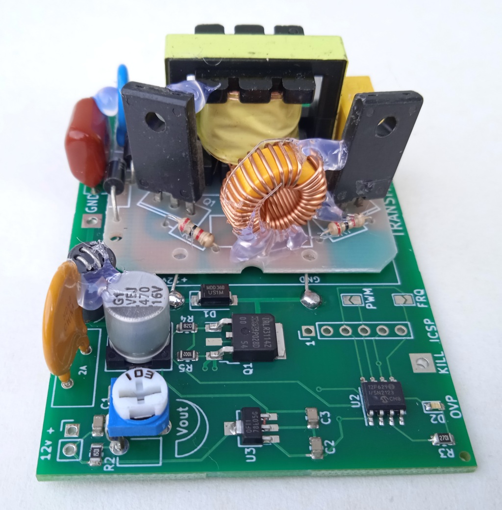
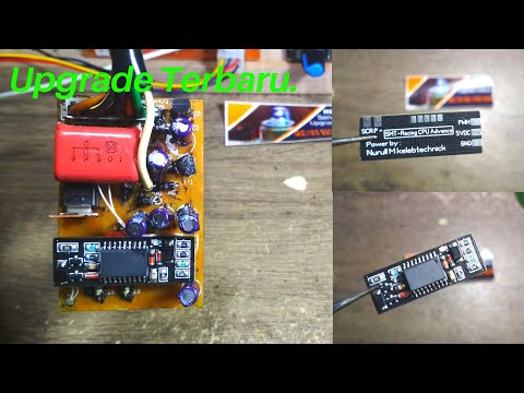
This circuit turns an AC-CDI into a DC-CDI.
An AC-CDI needs a working STATOR to charge. If the stator fails, let it be rewind or buy a new one is pretty expensive!
This circuit was designed to bypass the faulty stator by making High Voltage (around 200 to 400V) directly from the +12v battery.
When the internal SCR of the AC-CDI has been latched in ON state for a spark, only the voltage crossing a falling zero will turn it OFF again. In order to let the SCR return to blocking state, this circuit alternates ON and OFF states.

- 50 to 20,000 RPM
- 10 to 60mj
- Power supply voltage DC 12 volts
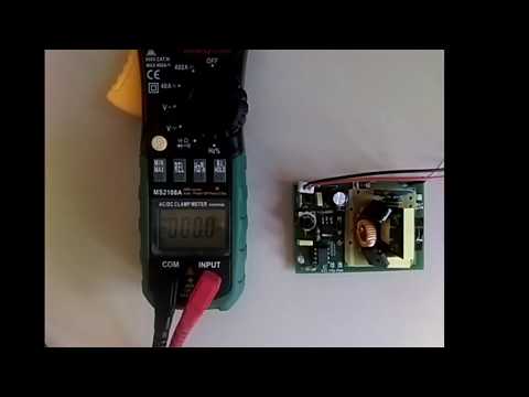
- Current drain: 60mA to 1.3A
- Output voltage: adjustable from 90 to 180Vdc
- Kill switch
- 1.5A resettable fuse for Thermal and overcurrent Protection.
- Ferrite choke to suppress HF electronic noise in electronic circuits.
- Common ground between 12Vdc and HV
- Dimensions: 75 x 50 x 25mm (3 x 2 x 1 inch)
Diagrams
Wiring to an ACCDI v2.7
Wiring to an ACCDI v2.8
Wiring to an ACCDI XT125-600
KIT: DC converter pinout
Jumpers
FRQ solder pad:
If open (default): Frequency of the circuit is 1000Hz (equal to 6 pulses/rotation at 10000RPM)
If close: Frequency of the circuit is 500Hz (equal to 3 pulses/rotation at 10000RPM)
PWM solder pad:
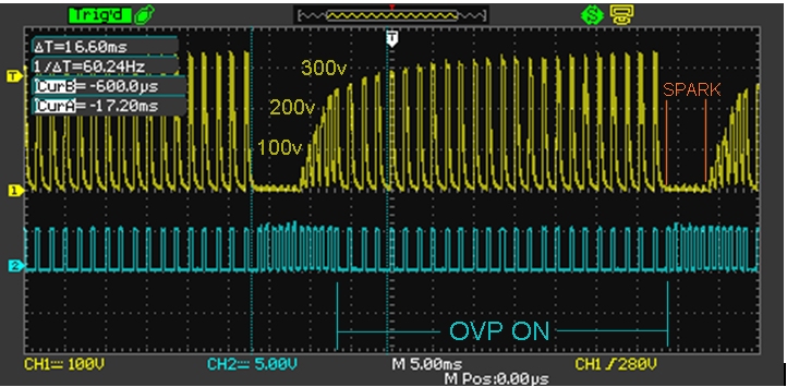
If open(default): HV generator alternate ON/OFF period at 50% (Maximum output voltage = +300Vdc)
If close: HV generator alternate ON/OFF period at 33% (Maximum output voltage = +200Vdc)
Led
– When the module is powered on, LED blinks 3 times meaning processor is OK.
– Led is OFF when output voltage is OK (not too high)
– Led turns ON when output voltage is too high and overvoltage regulation works.
– Led stays ON when KILL input is connected to ground to stop the DC generator.
Kill switch
Remove the KILL wire from the ACCDI and connect the Kill Switch to this Power module
If Kill input is connected to Ground: DC generator stops and Led turns ON. (Action Time: 1.5ms)
OVP
Over Voltage Protection: Turn the R2 trimmer to adjust the maximum average output voltage from +90v until +200v.
Led turns ON when OVP (aka regulation) is active.
Transistors need heatsinks if this unit run at 10.000rpm longer then 1 minute.
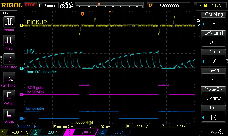
Blue: Mosfet Gate. Yellow: DC output
Power
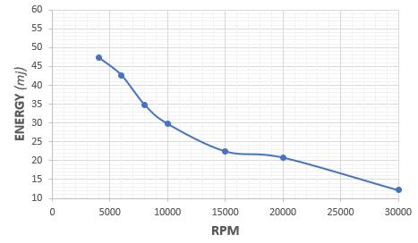
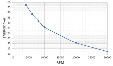
25mj are the minimum to get a spark.
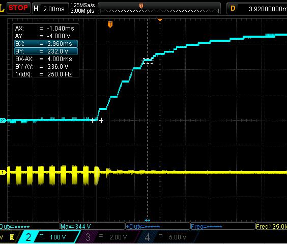
With trimmer at minimum:
With trimmer at maximum:
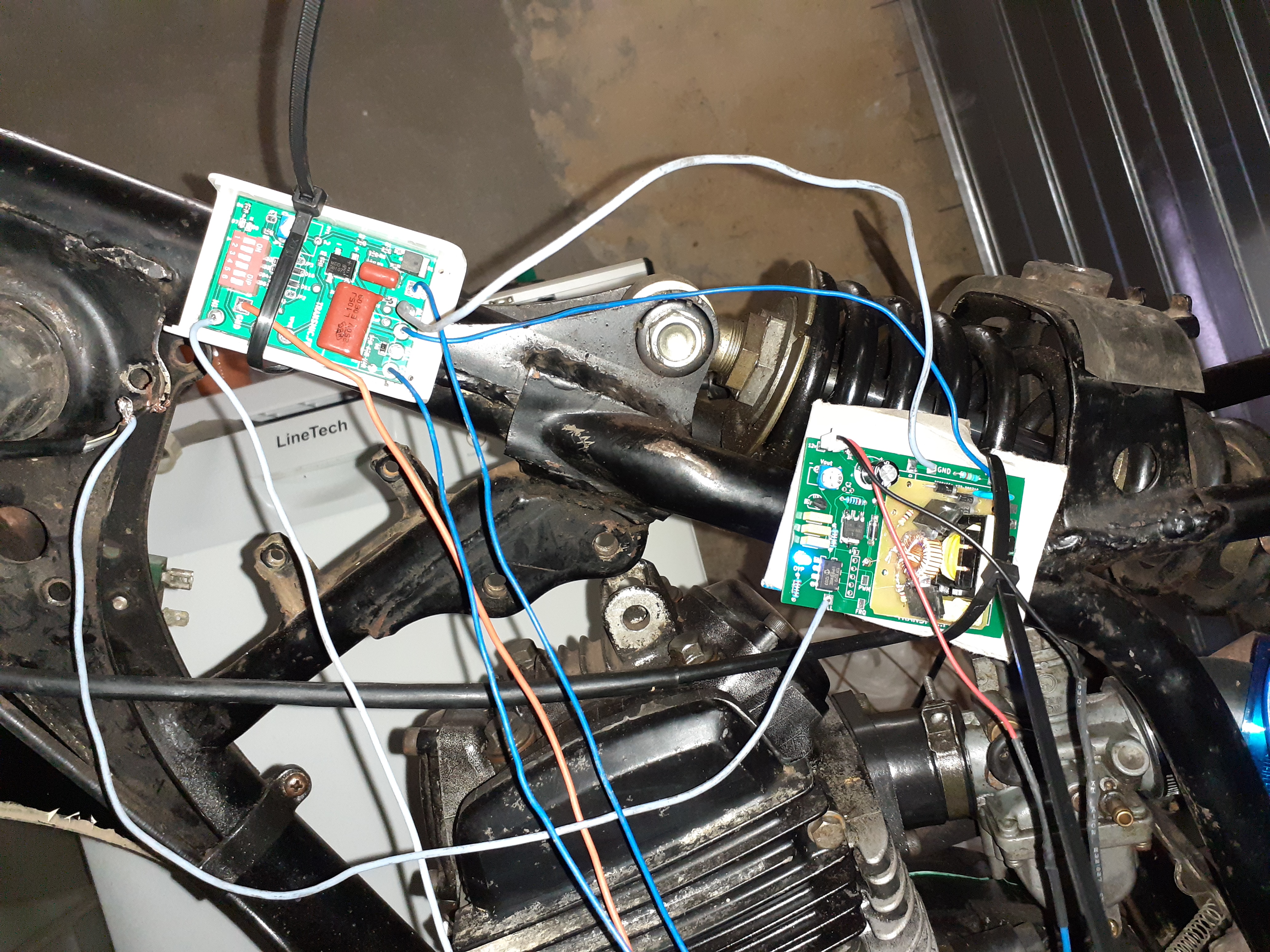
PHOTOS
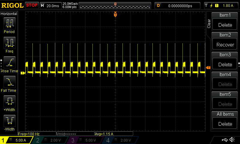
Current drawn at 6000rpm: Average: 1.15A with peaks at 2A and 9A:
VIDEOS
10.000rpm:
15.000rpm:
VERSIONS
- Version V1R2C1:
- First Version.
- Version V2R0C0:
- [soft] Improvements.
- Version V2R0C1:
- [hard] Change PCB layout.
- [soft] 2 PWM DutyCycles.
- [soft] Led blinks at startup.
- Version V2R1C0:
- [hard] Change components values.
- [hard] Change fuse type.
- [hard] Add self to avoid EMI noise.
- [hard] SMD components.
- Version V2R1C1:
- [hard] Change components values.
- [hard] Add capacitor to smooth the output voltage.
- Version V2R1C2:
- [hard] Change components values.
Hi Thierry
Sorry to write you again but I just saw that you are doing something similar to what I asked you in the previous email AC CDI 2DC CDI and I see that you do not have it for sale yet but you could send me the program and the PCB to go doing tests.
Thanks Jose Luis
Hi Jose, I contact you by PM at j…@sa….
BR
This is the same as what I produce
Hi
I recently bought this cirquit board
but there is no wiring diagram anywhere in the letter or on this site.
How do I connect the AC-DC board to the AC-DC CDI v2,5?
Please include a wiring diagram to the products you sell please.
Also, there is no way to contact you in another way than this forum
Hi
You have sent the wrong pcb, I ordered the DC AC converter, I received the dccdi pcb.
Hi,
I’m afraid not! Order #9391 dated 2020-07-05 was:
DC-Converter SKU: skudcconvert
Printed Circuit Board DC-CDI v7r6c0 SKU: skudcv7r6c0
Hi Thyerri
I received the printed circuit this morning and mounted it but I can’t get the output voltage to change or the LED to turn on and also if I try to change the frequency, I don’t see any change in the oscilloscope.
Am I using the V2R0C0 software on the printed circuit you sent me? Could this be the problem?
>I don’t see any change in the oscilloscope.
WHERE ?? I cannot guess where you hook the probe
>Am I using the V2R0C0 software on the printed circuit you sent me? Could this be the problem?
No but I’ll send you last V2R0C1 where led blinks 3 times if PIC and programing are OK.
Hi Thierry
I just tried the new software and it seems that it works when I regulate the potentiometer the Led turns on. I give you the voltage measurements that give me a Maximum 184V and at 130V the Led turns on and the minimum is 95v and consumption is at 0.07Amp. So far I think everything is fine but now I have another problem that had not arisen before and is that when I connect it and without giving any pulse at the PIKUP input on the CDI.
The AC CDI 2 DC CDI generates pulses in the CDI with constant frequency and I have changed the software to the old one I used before and it does the same.
And I did another test with an inverter with a normal 220V output transformer and it works perfect. Could you help me fix it.
Thanks a lot
Then the AC to DCCDI module is working fine with V2R0C1 firmware.
>when I connect it and without giving any pulse at the PIKUP input on the CDI.
You are ignoring the power of EMI/Electrical noise !
DC converter is a high speed switching device and it makes a lot of surge!
When you let the CDI pickup input, it act like a antenna and trigger on every spike in the air !!!
NEVER NEVER let input disconnected when dealing with DC inverter!
>a normal 220V output transformer and it works perfect
Of course a simple 220v main transformer is sinus and just 50Hz , not square signal and 1KHz ! So it doesn’t make parasitic noise!
Hi Thierry
I have almost achieved it, it works quite well, although it still has some interference and I want to ask you a question.
The inductive shock that goes into the 12V input of the CDI can be 10mH.
The main problem has been the high coil I was using has some leakage and HF pulses of more than 600 mV were coming out and for now I have been able to lower them to 200 mV but it already works.
When I have it solved I send you an email
Thank you
Hi,
OK and what was the question? 🙂
You can try a 10mH but HF Ferrite bead inductor are around 4uH like this one.
BR
Hi Thierry, i am joop from nl.
Can the dc inverter power a three cilinder ac cdi? 3 seperate cdi’s
Hi,
yes and no. Power matter !!
Look at the power graphs I added. CDIs need 25mj at the minimum, the graph shows 25mj = 15000rpm on 1cyl then it will be limited to 5000rpm MAX on 3cyl
Thanks! Ok my bike has a bad lowspeed winding so the higspeed winding will take over above 3000rpm. 🙂
Would like to have a more powerfull inverter to loose my heavy magnet from the crank for my triple dragbike. (max 10.000rpm) or i would buy 4cpl units from you…
Maybe you can email me?
Thierry!
How did you caclulate the stored energy?
With a scope and formulas here: https://transmic.fr/2016/07/14/dc-cdi-89c2051/
Hello,
Is it possible to connect this product to the original CDI of a yamaha 600 XTZ (TENERE) from 1986?
Will it make it easier to start the bike?
Thank you.
Hi,
I’m not sure as this CDI as a special feature to extract some volts from the high voltage coil to power the internal circuitry and IC.
Switch to TCI if you want a easier start but OFC it needs a fully charged battery and another ignition coil.
Hello Thierry. I own a bike parts store and It is always a pain in the arse to sell Cdi’s to empírical technicians who don’t know how to properly hook them. There is also lots of brands and ignorance about the topic, as people is not used to read wiring diagrams to plug components. I would like to have a way to test Cdi’s before selling them. I already know how to test DC cdis as one only need a Battery, HV coil and its everything. I have some general knowledge in electronics, as did some studies in electronics engineering. My major concern is how to test AC CDIs and TCIs. As I doesn’t have an AC source with their frequency changing as RPMs vary to simulate stator supply. Power source from home is only fixed 60 Hz and I believe that source from stator vary as RPMs increase. 7200 RPM = 120 RPS = 120 Hz. My point, Thierry, is that I’d like to buy some of your products which would allow me to test Cdi’s in front of my customers and avoid misunderstandings. Which one could you recommend me to test AC CDIs and TCIs. I have not read much about TCIs, but I believe they function more or less like a DC CDI. Thank you for your response and sorry for my long text. I forgot to mention that most of the bikes I sell parts to are between 100 and 200 cc from Indian and chinese brands.
Hello Mauricio
I totally get what you feel with customers who think they know but they don’t…
To test DC-CDI or TCI you need quite the same things:
– a 12v battery
– a capacitive ignition coil for DCCDI or an inductive ignition coil for TCI
– a pickup signal that could be a real pkp in front of a rotating magnet or a pickup simulator
To test AC-CDI you need
– a capacitive ignition coil
– a pickup signal
– and a High voltage source.
You are totally right, as the stator are 3,6,8 or 12 rotating poles, the frequency depend on the number of poles and of course of the engine speed.
Economical version: you can use the 60Hz of the main power but wont be able to rev about 6×60=3600rpm
 from the FAQ page
Months before I had this simulator that drove a HV generator: https://transmic.fr/2020/07/13/cdi-tci-tester-v62/
The frequency doesn’t change with RPM but in 99% of the cases CDI don’t care.
I don’t make it any more, it was too specific and only an handful of mechanics were able to understand how it worked….
Thank you for your reply. I’ d like to fully test AC CDIs throughout all its revolution range, including beyond 3600 rpm. I think I’m able to implement a NE555 circuit to simulate pickup coil. I also think about showing the output using an analog tachometer reading the CDI output to express changing RPMs. My main limitation is varying frequency AC supply with frequency varying from 0 to 200 Hz and amplitude between 100 and 200 volts. Don’t you make the varying AC source anymore? Or it doesn’t allow to vary frequency beyond 3600 rpm. Thank you in advance. Or is the component from this blog entry the device that is suited for my needs, please clarify to Me. If such is my case, I will buy. How much would it cost the shipment to Colombia?
Excuse me, maybe I didn’t understand the last part of your reply. It says that the HV generator doesn’t change its frequency and in most cases CDIs don’t care. That was another concern for me, how the HV generator was able to adjust its frequency to match pickup frequency, because I think somehow pickup and HV supply must be sincronized, as in a rotating flywheel the magnet energizes the same coils from generator and pickup on stator. And this last is crucial for the negative part of the sinoidal wave from supply to turn off internal SCR from AC CDIs.
In my old simulator, pickup signal and HV voltage were synchronized by the same processor.
If you use this part above (AC2DC) to power your DUT, the frequency will not change and will not be synchronized with pickup. It’s not perfect and can be heard in the spark sound BUT it works because this HV generator quickly regularly stop the power to allow the internal CDI thyristor to turn off.
Building a electronic generator able to change the frequency AND the voltage between 100 to 200v AND be syncronized with pickup would be VERY VERY difficult to build and SO expensive that it has no point to build one!!
A stator+rotor fixed on a lathe is hundred time cheaper and better.
>I think I’m able to implement a NE555 circuit to simulate pickup coil.
NE555 just make positive pulse. Not short sinus signal then nothing during the rest of the period. But it’s an inexpensive solution. Try it !
Ok, now my doubts have gone. I will buy your ACCDIToDCCDI converter
Did you ever pull out the thyristor and test it separately (like a curve tracer or classic forward/reverse test) to check if it’s still firing reliably?
I don’t understand. There is no thyristor on this device !