This AC-CDI is EOL
Features
- Programmable AC-CDI
- For ONE or TWO* cylinders
-
For [2 strokes engines] and for [4 strokes engines with wasted spark*]
* On 4stk engines with 1 pickup on the crankshaft, one spark occur at compression stroke and one at exhaust stroke. Firing in the exhaust stroke is a wasted spark. Hence the name…
- 80MHz MicroController control unit
- Easy programming with Micro USB Type B connection and terminal console
- Compatible Windows, Linux, Mac, (some Android)
- One customizable ignition timing curve
- Rev from 10 to 30,000 RPM
- 0 deg advance from 1 to 500 RPM (to avoid kickback)
- Adjustable timing in 13 steps from 500 to 20,000RPM
- Soft rev limiter.
- Temporary Legal rev limiter.
- Stator can be half or full rectified (for more power and ground isolation).
- 1 input for an inductive pickup (VR) or Hall type or Points
- Pickup polarity can be set to Positive, Negative or Automatic detection.
- 1 output for a Capacitive coil type.
- Non volatile configuration
- 12v Tachometer output (Even 12v)
- Kill switch input
- Charging voltage can be 100 to 600Vac
- Power supply voltage DC 10 to 16 volts
- Current drain: 100mA
- Protected against reverse supply voltage
- Available as a ready-to-use device in the SHOP section
- Dimensions: 100 x 60 x 25mm (3.9 x 2.4 x 1inch)
- Plastic box potted for Electrical insulation, Protecting components from mechanical shock and vibration, thermal shock or Moisture
- 15cm(6”) 1.5mm2(16AWG) wires soldered with 6.3mm automotive female connector
- Source not available
- Made in France
Cylinders:
* Twin-cylinders at 360° crankshaft angle:
The engine works with WASTED spark.
If there is ONE twin coil:
=> This AC-CDI works.
See: CDI compatibility
Remember that ignition coils are different from TCI to CDI system
– CDI coils have low inductance and impedance around 0.5-0.8ohm
– TCI coils have higher inductance and impedance around 1-3ohm
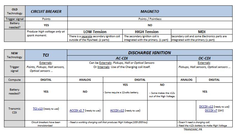
Remember there are AC-CDI and DC-CDI…
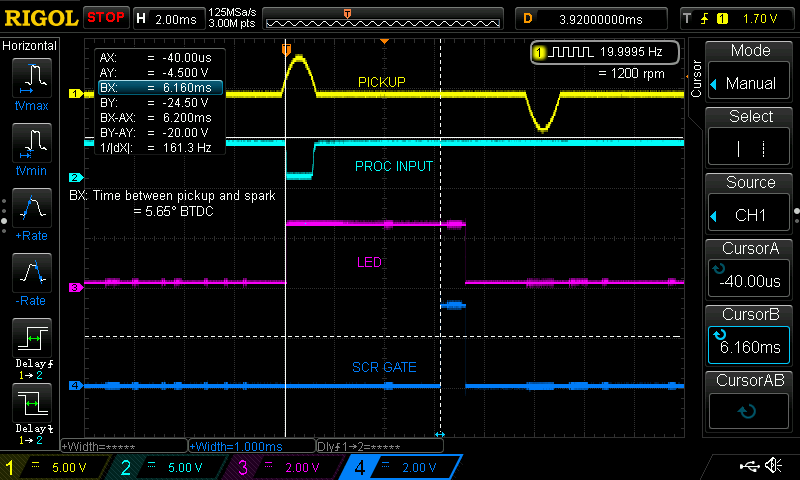
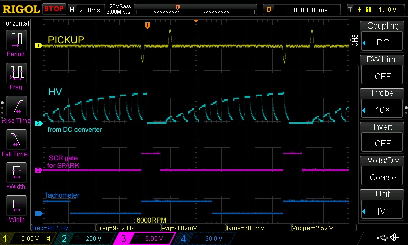
Pickup:
A pickup (aka: VR, Variable Reluctor, Reluctor) is a sensor that have a signal wires and a ground wire.
It’s made of a coil of wire wrapped around a magnet. When a ferrous part passes by the magnet, the magnetic field is modified and a voltage pulse is created in the coil generating a sine wave.
– 1 input for inductive pickup with 1 signal per crank rev.
– Pickup must puts out 3 to 30Vac
– Points, reluctors, Hall sensor, optical sensors can be used as long as they give only 1 pulse per revolution.
– 3 wires digital Hall effect sensors need an external pullup resistor. The default voltage output is equal to Vcc (+5v to 24v). When a magnet passes in front of the sensor, the output voltage goes low and the ignition will detect the RISING edge meaning the trigger moment will be when the magnet LEAVE the sensor.
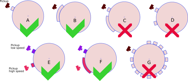
– This CDI works with 1 pickup and 1 reluctor (the metal strip on the flywheel) [A,B].
– This CDI works with 2 pickup and 2 bars [E,F].
– This CDI DOES NOT work with 1 pickup and multi-pulses pickup (ie 2 reluctors on flywheel) [C,D].
– This CDI DOES NOT work with 1 pickup and missing tooth flywheel [G].
Pickup Position
Even if it seems instantaneous, the flame front take some time to expand and ignite all the air+fuel mixture in the combustion chamber.
It becomes critical at high rpm. That’s why the ignition box should fire the spark a few degrees before the piston reaches Top Dead Center so the mixture explode just when the piston begin to back up. Generally engines need to be ignited around 30 to 40° BTDC (Before Top Dead Center)
It’s the ignition box job to calculate the timing according to the RPM. It makes the calculation as soon as it detect a pickup signal.
Therefore if the box need to ignite the engine 40° BTDC, the pickup signal MUST trigger the box BEFORE 40° BTDC.
So the pickup position can be 42° BTDC but also anywhere else!
Due to mechanical constraint, manufacturers put the pickup at different position, Yam XT600 was 36° btdc, Honda often uses 72° and so on.
As the ignition box has been triggered way before it needs to fire the engine, the box just wait until it’s time to fire.
How to calculate the Pickup Position?
- Find the TDC
- Read comment here and here
Pickup Polarity
Check the polarity of the pickup (Negative then Positive/NP or the opposite PN) with a Needle galvanometer (in milliAmp position) while kicking.
For a better understanding, this video can help.
Rev Limiter:
The last RPM value you enter is the “rev limit” that stop all sparks.
Legal Rev Limiter:
If you turn On then Off the KILL switch during the first 30 seconds after the engine started, a Temporary Rev Limiter will allow 3500RPM maximum for the current run.
After 30 seconds, Kill switch acts normally and stop the CDI.
After the bike has been stopped and restarted by the Master Ignition Key, the CDI runs without restriction.
In countries where 50cc are strictly restricted, the bike seems legal in case of control…
It can also be handy if a beginner rider tries the bike.
Ignition timing
– Draw the ignition timing curve into this XLS sheet.
Terminal console
- Windows
– Use a Terminal Software as CoolTerm or Teraterm or Putty or Kitty .
- Android
– Use Serial USB Terminal by Kai Morich and a Male-Male USB type-C OTG connector to USB micro-B. (video)
The phone must be OTG compatible with OTG turned on:
settings——additional settings—–enable/disable OTG.
- Mac
– Shell commands:
terminal

ls /dev/*usbserial*

screen /dev/cn.usbserial-xxxxxxxx 115200 -L

screen /dev/tty.usbserial-xxxxxxxx 115200
- Linux
– Use a Terminal Software as CoolTerm or Putty.
– Use Shell commands to find the COM-port:
tail -f /var/log/syslog | grep USB

dmesg | egrep --color 'serial|ttyS'

ls /dev/ttyUSB*
Port Configuration:
sudo su

stty -a </dev/ttyUSB0

stty -F /dev/ttyUSB0 cs8 115200 time 10
Connection to the device:
cat /dev/ttyUSB0 & cat > /dev/ttyUSB0
HowTo setup
Wiring
Ready-to-use unit:
For Half-Rectification and Common ground.
For Full-Rectification and Isolated ground. (More power)
PHOTOS.

VIDEOS
Setup with Android app:
MBX 125 onboard with programmable CDI v10:
Connection to the box:
Setup a ignition timing:
Change the ignition timing:
Test of an ACCDIv10:
ACCDIv10 powered by AC2DCCDI (DC converter)
VERSIONS
- Version v10r0c0:
- First Version.
- 5 seconds temporization to detect console.
- Wires come out at 90degrees.
- LED on the length side.
- Version v10r1c0:
- Automatic detection of the console.
- Wires come out at 180degrees.
- Stator can be half or full rectified.
- Version v10r2c0:
- Square +12v Tachometer output.
Features
- Programmable AC-CDI
- For ONE or TWO* cylinders
-
For [2 strokes engines] and for [4 strokes engines with wasted spark*]
* On 4stk engines with 1 pickup on the crankshaft, one spark occur at compression stroke and one at exhaust stroke. Firing in the exhaust stroke is a wasted spark. Hence the name…
- 80MHz MicroController control unit
- Easy programming with Micro USB Type B connection and terminal console
- Compatible Windows, Linux, Mac, (some Android)
- One customizable ignition timing curve
- Rev from 10 to 30,000 RPM
- 0 deg advance from 1 to 500 RPM (to avoid kickback)
- Adjustable timing in 13 steps from 500 to 20,000RPM
- Soft rev limiter.
- Temporary Legal rev limiter.
- Stator can be half or full rectified (for more power and ground isolation).
- 1 input for an inductive pickup (VR) or Hall type or Points
- Pickup polarity can be set to Positive, Negative or Automatic detection.
- 1 output for a Capacitive coil type.
- Non volatile configuration
- 12v Tachometer output (Even 12v)
- Kill switch input
- Charging voltage can be 100 to 600Vac
- Power supply voltage DC 10 to 16 volts
- Current drain: 100mA
- Protected against reverse supply voltage
- Available as a ready-to-use device in the SHOP section
- Dimensions: 100 x 60 x 25mm (3.9 x 2.4 x 1inch)
- Plastic box potted for Electrical insulation, Protecting components from mechanical shock and vibration, thermal shock or Moisture
- 15cm(6”) 1.5mm2(16AWG) wires soldered with 6.3mm automotive female connector
- Source not available
- Made in France
Cylinders:
* Twin-cylinders at 360° crankshaft angle:
The engine works with WASTED spark.
If there is ONE twin coil:
=> This AC-CDI works.
See: CDI compatibility
Remember that ignition coils are different from TCI to CDI system
– CDI coils have low inductance and impedance around 0.5-0.8ohm
– TCI coils have higher inductance and impedance around 1-3ohm
Remember there are AC-CDI and DC-CDI…
Pickup:
A pickup (aka: VR, Variable Reluctor, Reluctor) is a sensor that have a signal wires and a ground wire.
It’s made of a coil of wire wrapped around a magnet. When a ferrous part passes by the magnet, the magnetic field is modified and a voltage pulse is created in the coil generating a sine wave.
– 1 input for inductive pickup with 1 signal per crank rev.
– Pickup must puts out 3 to 30Vac
– Points, reluctors, Hall sensor, optical sensors can be used as long as they give only 1 pulse per revolution.
– 3 wires digital Hall effect sensors need an external pullup resistor. The default voltage output is equal to Vcc (+5v to 24v). When a magnet passes in front of the sensor, the output voltage goes low and the ignition will detect the RISING edge meaning the trigger moment will be when the magnet LEAVE the sensor.
– This CDI works with 1 pickup and 1 reluctor (the metal strip on the flywheel) [A,B].
– This CDI works with 2 pickup and 2 bars [E,F].
– This CDI DOES NOT work with 1 pickup and multi-pulses pickup (ie 2 reluctors on flywheel) [C,D].
– This CDI DOES NOT work with 1 pickup and missing tooth flywheel [G].
Pickup Position
Even if it seems instantaneous, the flame front take some time to expand and ignite all the air+fuel mixture in the combustion chamber.
It becomes critical at high rpm. That’s why the ignition box should fire the spark a few degrees before the piston reaches Top Dead Center so the mixture explode just when the piston begin to back up. Generally engines need to be ignited around 30 to 40° BTDC (Before Top Dead Center)
It’s the ignition box job to calculate the timing according to the RPM. It makes the calculation as soon as it detect a pickup signal.
Therefore if the box need to ignite the engine 40° BTDC, the pickup signal MUST trigger the box BEFORE 40° BTDC.
So the pickup position can be 42° BTDC but also anywhere else!
Due to mechanical constraint, manufacturers put the pickup at different position, Yam XT600 was 36° btdc, Honda often uses 72° and so on.
As the ignition box has been triggered way before it needs to fire the engine, the box just wait until it’s time to fire.
How to calculate the Pickup Position?
- Find the TDC
- Read comment here and here
Pickup Polarity
Check the polarity of the pickup (Negative then Positive/NP or the opposite PN) with a Needle galvanometer (in milliAmp position) while kicking.
For a better understanding, this video can help.
Rev Limiter:
The last RPM value you enter is the “rev limit” that stop all sparks.
Legal Rev Limiter:
If you turn On then Off the KILL switch during the first 30 seconds after the engine started, a Temporary Rev Limiter will allow 3500RPM maximum for the current run.
After 30 seconds, Kill switch acts normally and stop the CDI.
After the bike has been stopped and restarted by the Master Ignition Key, the CDI runs without restriction.
In countries where 50cc are strictly restricted, the bike seems legal in case of control…
It can also be handy if a beginner rider tries the bike.
Ignition timing
– Draw the ignition timing curve into this XLS sheet.
Terminal console
- Windows
– Use a Terminal Software as CoolTerm or Teraterm or Putty or Kitty . - Android
– Use Serial USB Terminal by Kai Morich and a Male-Male USB type-C OTG connector to USB micro-B. (video)
The phone must be OTG compatible with OTG turned on:
settings——additional settings—–enable/disable OTG. - Mac
– Shell commands:
terminal
ls /dev/*usbserial*
screen /dev/cn.usbserial-xxxxxxxx 115200 -L
screen /dev/tty.usbserial-xxxxxxxx 115200 - Linux
– Use a Terminal Software as CoolTerm or Putty.
– Use Shell commands to find the COM-port:
tail -f /var/log/syslog | grep USB
dmesg | egrep --color 'serial|ttyS'
ls /dev/ttyUSB*
Port Configuration:
sudo su
stty -a </dev/ttyUSB0
stty -F /dev/ttyUSB0 cs8 115200 time 10
Connection to the device:
cat /dev/ttyUSB0 & cat > /dev/ttyUSB0
HowTo setup
Wiring
Ready-to-use unit:
For Half-Rectification and Common ground.
For Full-Rectification and Isolated ground. (More power)
PHOTOS.

VIDEOS
Setup with Android app:
MBX 125 onboard with programmable CDI v10:
Connection to the box:
Setup a ignition timing:
Change the ignition timing:
Test of an ACCDIv10:
ACCDIv10 powered by AC2DCCDI (DC converter)
VERSIONS
- Version v10r0c0:
- First Version.
- 5 seconds temporization to detect console.
- Wires come out at 90degrees.
- LED on the length side.
- Version v10r1c0:
- Automatic detection of the console.
- Wires come out at 180degrees.
- Stator can be half or full rectified.
- Version v10r2c0:
- Square +12v Tachometer output.
Hi Thierry.
When its available to buy ?
Hi Nuno,
A prototype has been sent to Canada for real tests on a XT200 during December.
If everything is OK I expect to sell it in January 2020.
I’ll be very interested in how it works out on the xt200. I have 2 of them I’m rebuilding and have been looking for a good cdi solution. Thank you so much for all of this.
Hi Theirry,
I am interested in the new ac-cdi with the wifi receiver when is this available?
Greeting Mark
Hi Mark,
Beware ! AC-CDI v10r0c0 dont use Wifi but use direct USB connection for setup.
The 2 last prototypes are available now in the Shop and I going to order some new PCB for the modification I had to make. (AC-CDI v10r1c0) So the next sell will be in April…
I had good feedback from the guy who tested it on Yamaha XT200 – 1982. Some videos will come soon.
Regards,
Th
PS: ACCDI v9 was Wifi but it’s End Of Live now. ACCDI v10 is much more accurate than v9
Hi Thierry how’s it going? When is this cdi going to be available?
Hi,
thanks for your interest. The last one will be available next week and before 31 of May.
Then a period of 2 or 3 weeks for restock then a bunch of 10 should be ready for the 15th of June.
Hi Thierry,
I bought an AC-CDI v9 Last year that works pretty good in my XT600 but not really constant. So I want to try the new V10. When will it be available again?
Greetings
Markus
Hi Markus,
thanks for your interest.
Are you looking for a ready to use version (with box+wires+resin) at 70€ or a kit (all parts soldered on the PCB) but no box, no wires, no potting? The cost would be around 55€.
I have one kit ready.
Regards,
Thierry
you can also PM me at frtransmic [at] gmail.com
Considering purchase.
Can I get a tachometer pulse?
Not with ACCDIv10r1c0. I have to add some extra components and modify the firmware.
In the next coming version there will be a tachometer output.
Will it be added if I purchase ACCDI v10 currently on sale and wait? Or will it be updated to another version or model (v11?)?
No I cannot add it.
I have to add parts then change the PCB. It should be available at mid-November as V10 Release 2
Thank you for your reply.
We are waiting for the next version!
I am very pleased to have found your website.
Currently I have the topic that my cdi is broken.
Unfortunately I don’t really know anything about cdi and am unsicer whether I need an ac-cdi or a dccdi.
I hope you can help me further.
The bike is a MUZ 500 with Rotax (single cylinder 500ccm 4 stroke engine)
As I read in the forum the CDI of the Yamaha SR500 fits.
But the CDI generates not only the ignition voltage but also a speed signal for the speedometer.
Now the question is for me which cdi is suitable and if there is a suitable variant on your shop.
You must first know what kind of CDI you are looking for !
Read: Differentiate ACCDI and DCCDI
I quite remember that this old bike was using a Yamaha ACCDI indeed….
Hello Thierry , thank you very much for your answer.
I have a circuit diagram ( http://www.miraculis.de/aw/mz/text/mz50r/schalt1g.gif )for my motorbike (year 1993 )
and I am now very sure that it is an AC CDI.
What is the timing for the ACCDI v10 Rev 2 from the current point of view?
If the new version is available by mid-November this would be good, because I have to get the bike ready to ride again in November, because it is at a friend’s place who needs the space again.
Best regards,
Frank
T
Hello Frank
Yes it’s an ACCDI but you have to know what each wire is for.
Why are there 4 wires from CDI to Stator (perhaps: HV for high revs and for low revs, gnd, and last one?)
and also why 3 wires to ignition coil?
I have ordered 20 PCB of new version V10R2, They will be there in November. Otherwise there is the last kit ACCDI v10r1 in the shop.
Best regards,
Thierry
When will the new AC-CDI V10 (tachometer pulse) be developed and sold?
ACCDI v10r2c1 has been developed. I just received the PCBs yesterday the 24th and I’m building and testing the first one. It should be in the shop this WE. I’ll shot you a Email when done 😉
Thank you for your reply!
I bought it!
By the way, is it possible to convert 12V of tachometer pulse to 5V? (12v→5v)
Should I use a resistor to divide the pressure?
I got your order Thanks! It will leave on the 2nd of Dec.
Yes you can use 2 resistors of 1k to divide to +6v (or only one resistor, the same value as tacho internal resistance)
Regards,
Th
Hi Thierry,
I’m also interested in one of the new cdi units.
can you please inform me per mail when the next available in shop?
I can also solder it by myself. so i need only the parts if this would be faster.
Best regards,
Frank
Hello Franck,
Two ACCDIv10r2 (with tachometer/RPM meter) will be available tomorrow the 29th of Nov.
I’ll send you an email.
Best regards,
Th
hello Thierry, could you possibly provide a cdi for an 89 yz250 engine? i have no idea what i need :-/
Hi,
it seems to be an ACCDI ref 3JE-85540-00-00
https://www.bikebandit.com/oem-parts/1989-yamaha-yz250-yz250w-electrical-1/o/m146661sch135001
What says the wiring diagram?
Take off the CDI and scan the stator connector, is it the same connection as 93′ YZ250 as shown here:
http://mybikemanuals.com/yamaha/yamaha-yz-owners-manuals/
Th
Bonjour Thierry,
je viens de commander la dernière Box AC-CDI V10. Elle sera pur une Yamaha SRX 600 année 1987, quelle à un ajustement de l’allumage de 12° à 36° avant T.D.C.
La vitesse à laquelle 36° est atteint est de 3800 tr / min (?4000).
Pouvez-vous programmer l’appareil pour moi avec ces valeurs?
Et: la SRX a un capteur double pour tôt et tard. Laquelle de ces bobines dois-je utiliser?
Merci pour ta reponse, cordialement
>la SRX a un capteur double pour tôt et tard. Laquelle de ces bobines dois-je utiliser?
il faut utiliser le capteur a 36deg BTDC pour les hauts régimes.
Regarde ici: https://transmic.net/2016/07/14/yamaha/ et là: https://transmic.net/images/sensors.jpg
I’ve bought an Analog AC-CDI and tested it on a SUZUKI GT500 (Twin 2strokes). I would like to upgrade to an AC-CDIV10, but it seems to be impossible to fit my bike with it (because of the rev limit at 20000 RPM). In fact, I don’t need so much revs (red zone begins at 7000 RPM, and max rev sould be 9000 RPM). So, despite the pickup gives 2 pulses per rev, I’m under the rev limit of the CDI ?Thanks for answer…
Hi, Does AC-CDI V26 works on a SUZUKI GT500 (Twin 2strokes)? It should but for sure a 2 stk need a different ignition timing that you only get with a programmable box.
The GT500 has 2 magnets 180° apart, so indeed you need twice the max rpm. As 2 * 9000rpm < 20.000rpm of the ACCDI v10 it's OK. Furthermore ACCDI v10 is capable of much more! I tested it at 30.000rpm. The limitation comes mainly from the charging system. (We can follow up by PM in french)