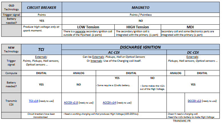
This AC-CDI is End Of Live
Characteristics.
- For ONE or TWO* cylinders
- Highly adaptable.
- Can handle different pickups coils (Yamaha,Honda,Suzuki,Kawasaki,Zongshen)
- Use the first pulse of the pickup signal for HIGH RPM, maximum power.
- Use the second pulse of the pickup signal for LOW RPM , idle and easy start.
- Works with 1 or 2 pickups.
- RPM when CDI jump from LOW to HIGH is adjustable.
- 2 LED indicators.
- Timing adjustment available for 2 strokes engines.
- 12v tachometer output.
- Need a working charging coil (stator) for the capacitor. (or a DC converter)
- Charging voltage can be 100 to 600Vac
- Doesn’t need a battery
- No rev-limiter (Tested at 20,000rpm)
- 2 power available: for engines below or over 350cc
Limitations.
This CDI only does the ignition task, it doesn’t use any safety like neutral and sidestand. It only uses Kill Switch.
- If any, connect Neutral switch wire to Neutral indicator.
- If you need “Side-stand security” then connect the Sidestand switch to the KILL input on this CDI.
- Only works with VR pickup (Variable Reluctance AKA pickup coils)
- Cannot work with Hall sensors or points.
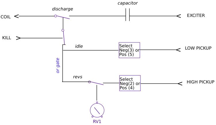
How does it works?
On an ACCDI based engine, the charging coil (AKA stator) puts out:
– LV (Low Voltage around 12Vac) for light and battery if any. (Lighting coil)
– HV (High Voltage around 100Vac) to charge the ACCDI. (Charging coil)
This AC-CDI only uses the HV coil to charge the big C1 capacitor through a rectifier bridge.
When the pickup is triggered, the CDI turns on a thyristor that discharge the capacitor inside the primary coil.
This burst of energy into the primary induce a high voltage of few thousand volts into the secondary coil, enough voltage to create a spark at the sparkplug contacts.
Here is a interesting video description of how a CDI works.
PICKUP
– This CDI works with 1 pickup and 1 reluctor (the metal strip on the flywheel) [A,B].
– This CDI works with 2 pickup and 2 bars [E,F].
– This CDI DOES NOT work with 1 pickup and multi-pulses pickup (ie 2 reluctors on flywheel) [C,D].
– This CDI DOES NOT work with 1 pickup and missing tooth flywheel [G].
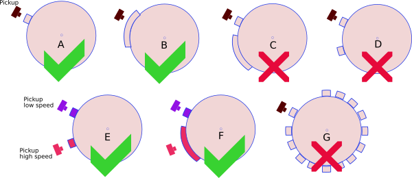
– When the engine has only ONE pickup, the 2 wires are connected to HI and GND inputs.
– When the engine has TWO pickups (for Low speed and High speed), the 3 wires are connected to HI, LO and GND inputs.
Pickup Polarity
Be careful: If the wires are swapped then the pickup polarity will CHANGE !
A genuine Yamaha pickup is often Positive first then Negative (PN) but if you swap the 2 wires of the pickup, the polarity will be Negative then Positive (NP) therefore the DIP switches setting for PN will NOT work anymore of course !
Solution: Rectify the pickup connection or use the settings for NP engines.
Example: PN if correct wiring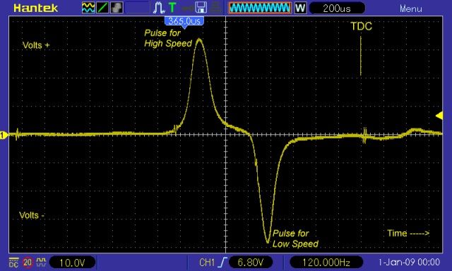 |
but NP when swapped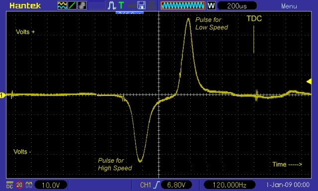 |
| On Yamaha, Kawasaki pickup is wired in order that the Rising edge of the bump on the rotor induce a POSitive pulse first. |
On Honda, Suzuki pickup wires are swapped so the Rising edge of the bump on the rotor gives a NEGative pulse first. |
|  |
COMPATIBLES BIKES
List of bikes with 1 pickup this CDI works on.
List of bikes with 2 pickups this CDI works on.
Not compatible bikes:
Yamaha YT250 (1995-) because it use a TCI
Yamaha XMax 250-500 scooter = TCI
Yamaha YZ400 (1978) = MAGNETO
Suzuki DRZ400 = DCCDI
Yamaha XT600E (1990-2003) [3TB/3UW/3UX/3UY/3WR/VJ01/DJ02/4PT] = TCI
Yamaha TT600 (1993-2005) [4LW/4GV/DJ01/5CH] = DCCDI
Suzuki Savage 650 = TCI
Yamaha SRX660 (1996) = TCI
HOW TO SET DIP SWITCHES?
You have to know if the bike has 1 or 2 pickups.
And for each pickup what is the polarity: PN (Positive then Negative) or NP (Negative then Positive).
Connect a scope between Ground and pickup wire to check the polarity.
If you don’t have a scope at hand (A PC can be used as a scope), you can see the polarity with an old voltmeter (see video above).
If you still don’t know :-/ You’ll have to test every possibilities… Follow those guides:
Tests all settings for 1 pickup. Tests all settings for 2 pickups.
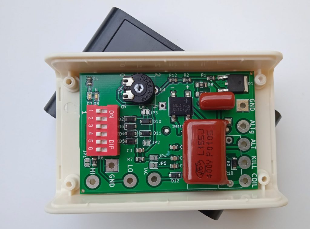
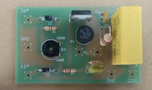
DIP SWITCHES positions
WIRING
CHARGING COIL
– If the charging coil is internally grounded, then connect the only wire to “ALT” input and leave “ALTg” not connected. Note that DIP SW N°6 will have to effect.
– If the charging coil is NOT internally grounded, then connect the 2 wires to “ALT” and “ALTg” inputs.
Order has no importance.
DIP SW N°6 ON: Less voltage. OFF position: More voltage.
JUMPERS
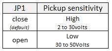
JP1: Sensitivity
This CDI needs a pickup that puts out 2 to 30volts.
For pickup that puts out more then 30volts, cut JP1 jumper pad.
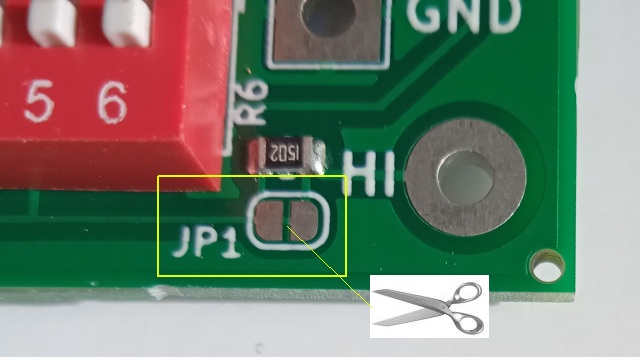
JP2+JP3: Lower advance at low RPM
If there is too much advance at LOW RPM, advance timing can be lowered (= spark closer to TDC) with JP2 and JP3 solder pads cut open.
Cut JP3 open for KTM engines.
2 STROKES
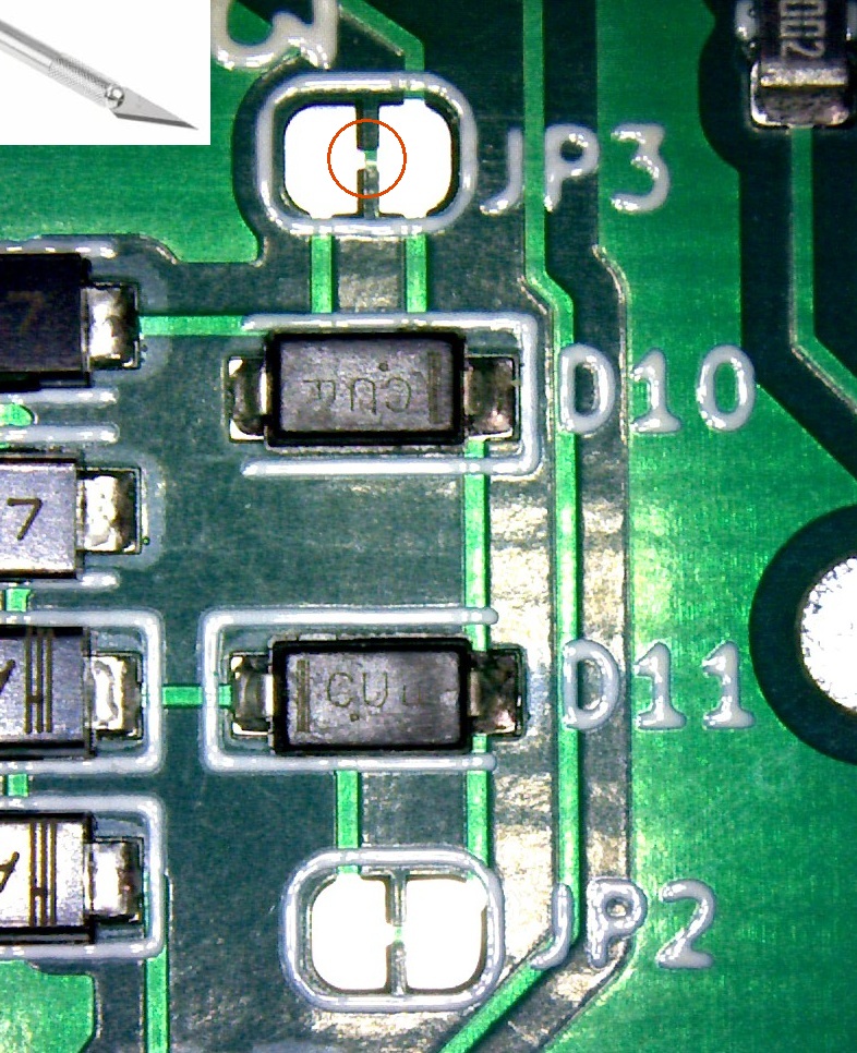
JP4, JP5: Advance timing for 2 strokes
On 2 strokes engines it’s necessary to lower the timing at HIGH RPM, this is done with JP4 and JP5
Small timing reduction over 3000rpm: Close JP4 with a soldered joint.
Medium timing reduction over 3000rpm: Close JP5 with a soldered joint.
Large timing reduction over 3000rpm: Close JP4 and JP5.
TACHOMETER
A tacho output is available. The output voltage is +12v (even if no battery)
Notice that it’s not a pure square signal.
Connect a tachomoter that does NOT need a 50% square signal (50% off, 50% on)
TIMING
It doesn’t have seamless advance, it jumps from LOW advance to HIGH advance.
The RPM when the CDI jump from Low to Full advance is adjustable with RV1 potentiometer.
– Run the bike at idle with RV1 at max value (4)
– Try to rev up the engine while slowly unscrew (toward 0) until the bikes wants to rev up.
– When she wants to rev up you’ve got the setup.
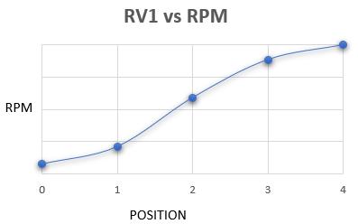
Example:
| 2200 rpm with RV1 at 4: CDI uses the second pulse = Low advance  |
2200 rpm with RV1 at 1.5: CDI uses the first pulse = High advance 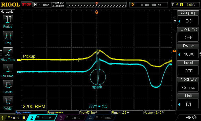
|
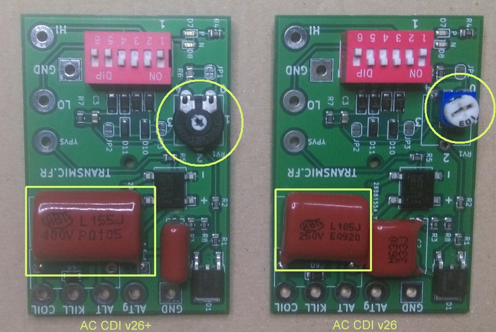
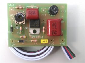
POWER
This unit is available in 2 models:
ACCDIv2.6 standard for engine from 50 to 350cc with a 1uf 250volts capacitor
or
ACCDIv2.6+ with 50% more energy for bigger engine from 350 to 1000cc with a 1.5uf 400volts capacitor and a high quality trimmer (Piher brand)
LED
LEDs have “N” and “P” labels.
They turn on when the CDI receive a Negative or Positive pulse on HI input.
Math
4 strokes 1 cyl= 0.5 * 1 = 0.5spark/rev (when no wasted spk)

4 strokes 2 cyl= 0.5 * 2 = 1spark/rev

4 strokes 4 cyl= 0.5 * 4 = 2sparks/rev

2 strokes 1 cyl= 1 * 1 = 1spark/rev (= 4 stk 1 cyl with wasted spk)

2 strokes 2 cyl= 1 * 2 = 2spark/rev
TROUBLESHOOTING
You will need a DC voltmeter. The best is an old “Analog Needle meter”.
Step 1
Download troubleshoot step1
– Don’t connect any pickup.
– Don’t connect the Kill Switch.
– Connect the GND plug of the CDI to the ground (minus battery or motorcycle frame)
– Connect the ignition coil to the COIL output of the CDI.
– Remove the sparkplug from the engine and connect the metal body to a GOOD metal frame (An unpainted bolt).
– Connect a DC voltmeter between GND(ground) and KILL pad.
– If the stator/charging coil IS NOT internally connected to ground, it has 2 wires:
– Connect any of them to ALT and the other to ALTg input of the CDI.
– DIP Switch 6 can be ON for full rectification or OFF for half rectification (Don’t hesitate to test both position).
– If the stator (charging coil) IS internally connected to ground, (One wire is already internally connected to ground):
– Connect the only output wire of the charging coil to ALT input of the CDI.
– DIP Switch 6 has no effect. (can be on or off).
Other DIP switches positions don’t matter for step 1.
Then:
– Kick start or electric start a few times to load the capacitor.
The voltmeter should raise up to 100 or 200Vdc then quickly decrease.
(Due to the capacitor discharging into the CDI and the voltmeter).
If not: Check grounds, connections, joints, charging coil (stator), change switch 6 position.
Step 2
Download troubleshoot step2
– Same connections as Step 1 (Still no pickup, no kill switch)
– Turn DIP Switches positions 1, 3, 5 to ON.
– Turn RV1 to the minimum resistance (Position: 0).
– Kick start or electric start a few times to load the capacitor.
– Once the main capacitor C1 is charged and the voltmeter shows 100 to 200Vdc, then in the same second:
– Connect the + 12v battery to HI input:
– Labelled “P” Led turns on.
– The big Capacitor discharge into the ignition coil and one spark must fire at the sparkplug.
If not: Check grounds, connections, joints, SCR, ignition coil, spark plug cables, spark plug.
Redo this Step 2 but this time connect the +12v battery to the LO input. (Led won’t light.)
Step 3
Download troubleshoot step3
– Same connections as Step 1 (Still no pickup, no kill switch)
– Turn DIP Switches positions 2, 3, 4, 5 to ON.
– Turn RV1 to the minimum resistance (Position: 0).
– Connect the pickup coil between a GOOD metal frame (ground) and HI input of the CDI.
– Kick start or electric start to load the capacitor and send trigger pulses:
– The main capacitor C1 is charged and the voltmeter should read 100 to 200Vdc.
– At the same time, when the piston approaches the TDC and passes in front of the pickup, a pulse is created by the pickup:
– LED blinks. (P or N or both leds according to the type of pickup)
– The pickup pulse then trigger the SCR and the big capacitor C1 discharges into the ignition coil, a
spark must fire at the sparkplug.
If not: Check grounds, connections, joints, pickup coil, RV1 is set at 0, reverse the 2 wires of the pickup coil.
VIDEOS.
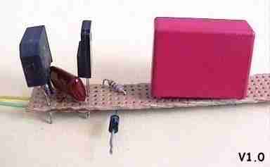
- Version 1.0:
- Version 2.1:
- Version 2.2:
- Pickup polarity (PN or NP):
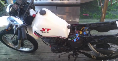
- Marty bought a 1984 wrecked XT600 without ignition and harness wiring.
Got it running again even if it seems like he has some carbs works to do…
- Analog CDI v2.4 on a XT125/1982:
- Analog CDI v2.4 on a XT400:
- Analog CDI v2.4 at 10,000rpm:
- Analog CDI v2.4 at 15,000rpm:
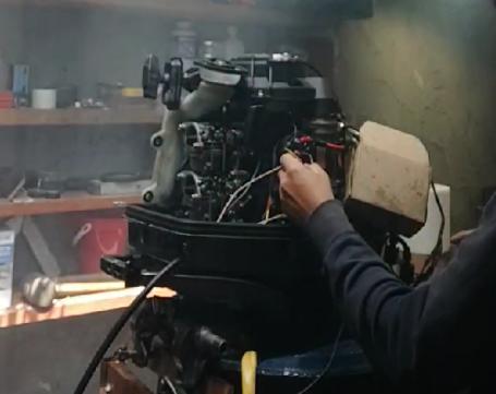
- 3 Analog CDI v2.6 on a outboard Suzuki DT30C (3cyl 2stk)
hello Thierry, i have a yamaha xt250 2valves 1980, i run the bike with no battery, i just have front\rear lamps drived by the AC circuit (bike is heavy modified for enduro ).. does this CDI will work on my bike or it needs a battery\DC circuit?
thanks
paolo from italy
If you had read this page you would know
v2.6 Characteristics.
For ONE or TWO* cylinders
Highly adaptable.
Can handle different pickups coils (Yamaha,Honda,Suzuki,Kawasaki,Zongshen)
Use the first pulse of the pickup signal for HIGH RPM, maximum power.
Use the second pulse of the pickup signal for LOW RPM , idle and easy start.
Works with 1 or 2 pickups.
RPM when CDI jump from LOW to HIGH is adjustable.
2 LED indicators.
YPVS output to drive an YPVS box.
Need a working charging coil for the capacitor. (or a DC converter)
Doesn’t need a battery
No rev-limiter (Tested at 20,000rpm)
Running unit available in the SHOP.
thankyou, i was in doubt for this sentence:
-Need a working charging coil for the capacitor. (or a DC converter)
is the charging coil the one that drives the Dc converter and charges the battery?
do i need a DC output to drive the ignition?
ACCDI are loaded by an AC High Voltage charging coil.
Stators for ACCDI based engines have 2 coils:
one LV (low volt.) 12Vac for light and battery if any.
one HV (high volt.) 100Vac to charge the ACCDI
ACCDI v2.6 use HV output usually.
See the wiring: https://transmic.net/ACCDIv25/cablagePCB.pdf
ACCDI 2.6 can also use an external DCconverter that step up the 12Vdc to 100Vdc
Hi Thierry!
I got now one V2.6, and I thinking about that may I should change the potmeters to these parts which are on the new picture . It’s matter something which part in it?
No there is no need to change anything.
Can u help me with a 83 XT550 wire connections. Why ALT on board twice? Thanks
1 alternator then 2 wires for HV (generally R and Br for XT550) that go to the 2 ALT inputs.
See Wiring and troubleshoot up there.
Th.
Hi Thierry!
On my V2.6 ACCDI the D9 “A7” type diode gone short to the ground at of this capacitor side, and it’s burnt out.
Can you tell me what kind of diode can I repair with? And It’s possible to have other not visible damage in some of the other parts?
Hi Takacs,
Thanks for the feedback. The diode is a 1N4007 You can remove it and replace it by a short between Anode and Kathode.
No other parts I can think of… It seems like high voltage jumps from diode to GND. I’ll increase isolation!
What is the bike?
Thank you for your answer!
It’s an XT 550 from ’83.
I thought only what if may the diode function is to protect the capacitor and then probably damaged that too.
But then I will make a short there, thanks the help.
Hi
Great product! My XT600 lives again!
I have a slight problem though as it won’t rev now past 3000.
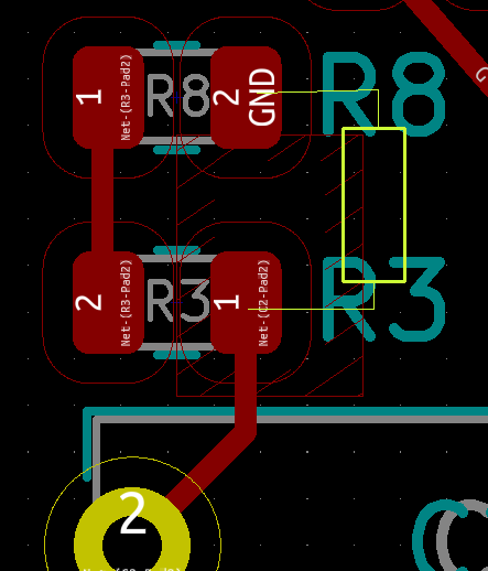
It looked like R3 burnt out.
Any help would be appreciated
Hi,
Thanks, cool!
Re R3 yes that can append sometimes and coming version will improve this point.
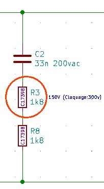
R3 is rated for 150 and an overvoltage of 300v that can be reach sometime or if bad cnx with the sparkplug. (check this out)
You can replace R3 (3k3) by 2 Through Hole 1k8 0.25 or 0.5w resistors in series between C2 leg and GND.
Thierry,
Thank you for your help.
Once again top product, at a great price.
Regards
Lane
I have a question for you about this unit! I am looking for an alternative for my 1995 & 1996 KX125. Would this work on my bike?? please let me know what the difference would be for a single cylinder 2 stroke!
Sorry for the last question did not read everything that you have attached! I think this will work after reading everything. I am going to try it and see how it goes! Will respond on how things work for me and let you know what happens! 1996 KX125
No problem. Do you have the wiring diagram of this model? I flipped though the www and saw there are some Kawa CDI WITHOUT external pickup!
If yours is in this case there is a workaround to do, contact me in case…
Hello
I want to make CDI ignition system for an old bike.
I need to know how advance curve can be adjusted. At startup mode advance should be 0 deg, max advance is 46 deg.
Regards
Ivan
Hi, No you cannot adjust the advance curve. You need a DIGITAL CDI (with processor inside) to do that: ACCDIv10, ACCDIv7
Th
Thank you for your answer.
Few more questions.
1. Is Digital AC CDI can work with kick starting or need to be DC CDI?
2. Is it important leght of the rotor signal protrusion – short or long?
1) what do you mean? DC CDI needs a battery.
2) the question is: “Are the ignition settings important?”
This is ignition 101. No offense but if you want to create an ignition for an old bike you have to master differences between ACCDI, DCCDI, TCI, Magneto and DEEPLY understand how an ignition works !
PS: and I cannot give private lesson 🙂
Thierry,
The AC-CDI v2.6 unit arrived! Wow, what a neat piece of hardware you have made here, Sir.
I read the FAQ, but I still have a question, can you please tell me what the proper settings should be for the DIP switches? As shipped it arrived as:
1: off
2: off
3: off
4: on
5: on
6: off
I checked your write-up here (https://transmic.net/2016/07/14/yamaha/) about Yamaha magnet signals, I was not sure if my switches are configured properly. Looking at the DIP settings above as it arrived in the mail today, can you tell me if I have these set up optimally for my 1982 Yamaha XT250? I appreciate any assistance that you can give to me!
Thank you,
Donovan
Thanks Donovan, it’s kind of you.
I NEVER set up switches beforehand as customers almost never said which bike they have.
it’s just the set up for tests I used lately.
Pls refer to https://transmic.net/wp-content/uploads/2020/11/modeles_et_switch.pdf
Anyway, I tend to believe XT225 is best then XT250 setup and would appreciate any feedback on it…
Regards,
Th
Would it be possible to replace the ignition of a classic motorcycle with fixed advance?
what kind of ignition coil do you need?
To convert from Magneto to ACCDI, you need:
– a stator+rotor to charge the CDI
– an external pickup (as point are closed by default)
– a ignition coil for CDI ( x100 ratio, around 1ohm primary)
if you want a full adjustable timing then you also need DIGITAL CDI: ACCDIv10 or v7.
ACCDI v26 will have static timing with Hall sensor and a more adjustable timing with VR pickup.
I have an electronic ignition without pick up. The coil with the positive wave charges the capacitor and with the negative one activates the thyristor that is in the outer high coil. Could you use any of your circuits that would be variable using the negative wave?
Which bike?

ACCDI v2.6 can work with an engine WITHOUT pickup, using the positive wave of the sinus to charge the capacitor and the negative wave to trigger the spark.
Then setting should be:
Connect “ALT” to “HI” through a 1000 or 2800ohms resistor.
1,3,4,5,6 = off
2 = on
JP1: open (jp3 open perhaps)
RV1 adjust the level of voltage that trigger the thyristor.
Hello, at the end of 2020 I bought ACCDI v2.6 from you for my 1985 XT225 Serow.
I want to thank you, it works great. Thank you for suggesting then about the polarity of the ignition sensor connection. Everything works without any changes in the wiring. Am I correct in understanding that the RV1 resistor adjusts even if one ignition sensor is used? Although there is no need for this yet, I would like to know it just in case.
Hello,
Yes I remember. you ordered on Ebay from Kazakhstan.
I’m happy that your XT225 is running again.
Yes RV1 is always in use because it uses LO input
1 pickup is connected to LO input and 2 pickup are connected to LO and HI
Hi and thankyou for this fantastic item hat my wife bought me in early nov 2020. I have some questions. My early xt200 that I’m restoring after finally wiring up and what I thought was the correct dip settings the bike started and idled ,”bonus ” then went to rev it up and all it would do is back fire. Weeks and weeks go by same thing and check all mechanical , cam timing etc, clean carby etc etc etc. Finally this week I Check dip settings oops wrong, now set to your suggested settings , same thing. Now set to XT 125 dip settings an now idles and revs up so far then misfires. I have seen spark jump from and around the R3 area and disappear. Long story short what have I done and can I fix it.
Hi, Thanks. I’m glad your bike is on the road again.
No worries, you didn’t do anything wrong. I think you PCB is ACCDIv2r6c2 when there was only one R3.
I noticed that under high voltage (related to dip sw N°6) R3 can broke up then short the HV.
As a workaround, remove R3 but I advice to keep the snubber on so replace R3 by a TH resistor 1k8 to 3k6.
Now ACCDIv2r6c4 comes with 2 resistors to increase breakout voltage:
Hi and thanks for the info, I have version 3 and as i don’t completely understand what you mean I will have to find someone who does. Will this fix the miss fire at say 3000 rpm and above or am I looking at the bike electrics eg stator , pickup coil etc.
Hi,
will this fix? Hard to say from distance. There is nothing complicated
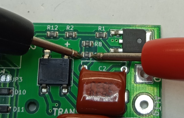
first : measure R3 and R8 values: it must be 1k8ohm (1800ohm) each. If it’s not then R3 and/or R8 are destroyed
second: if one of them is destroyed, unsold it with a small soldering iron
(we’ll follow up on PM) Also tell me what your current setting is.
@ Malcolm
I got the picture and they seem to be broken, so an overvoltage certainly occurred.
Just unsold and replace them with only one classical (Through Hole) 1k to 3k resistor and from set DIP switch 6 in ON position. (for lower voltage)
Hi. I purchased an ACCDI V2R6C2 in September 2020 for my 1980 XT250G. I wired it up and mounted it inside the original metal box. The bike fired up right away and seemed to run fine. But now it misses and the timing light shows that firing is inconsistent. I have another CDI box that works fine and the timing light shows steady firing at the F mark. So I do not believe it is a problem somewhere else in the system. The problem is with the ACCDI. The bike has only run for a few minutes in the garage (since it has been winter).
Upon reading the above conversation with Malcolm, I see that R3 on my unit is failed (open circuit) and will need repair. This looks like a difficult task as the existing resistor is not through hole. I am concerned that without professional repair, the CDI could be damaged and become unusable.
As this is known problem with this PCB and that it has been redesigned with the addition of R8, do you offer any exchange for these defective parts?
Please advise
Hi,
Pretty rare but R3 could be destroyed on ACCDI V2R6C2, that’s why I added a second one.
As R3 blown away and is now open circuit there is not need to remove it!
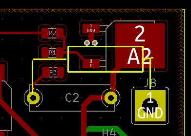
You can easily add a 1k to 3k9 TH resistor on the copper side soldered between C2 left leg and ground:
If you failed to do so, feel free to PM me at frtransmic@gmail.com to check your order and address then arrange a sending of a new naked ACCDI V2R6C4.
Regards,
Th
Hi again.
I installed the new resistor per your instructions and I am getting consistent spark at the correct timing “F” mark. The advance is working although I may need to adjust the RV2 settings after riding it. Hopefully that solves all issues. Now I can get out and ride!
Thanks again for the solution.
Hi,
Excellent. You did it well ! Now you know how to repair it.. Ride safe.
Regards,
Hello
I would like to build this circuit!
Where is its circuit?
help me
Hi,
It’s only available in the shop already built.
Hello again
It is not possible for me to buy a physical PCB !!!!
Can I buy a schematic or altium file???
Or give it PCB images
Please …
help me
Sorry partlist and schematics are not available.
The only one available is the old ACCDI v22 here
Hi! First of all I have to say I love your product, I have been using the v2.4 version of this cdi on a gn400, and have recently bought two of the v2.6 versions.
However this time I have a problem that I for the life of me resolve on my own. I have read and understood all of the v2.4 and v2.6 pages but I can not get this working. I have a suzuki dr500s with a single pickup. I did not know the polarity but did not want to open the engin to check it so I used trial and error, the bike started flawlessly and worked great on settings 1 5 6 on, so I started to tune for high rpm and turned on 1 2 5 6, turned rv1 to 2, and the bike revves great standing still in neutral, however I can not get it past 90kmh on the street. I have since tried many different combinations but nothing helps me get past 90kmh (it feels like I hit a rev limitter wich i know doesn’t exist). The carb is clean, the bike has fresh gas and the engine is solid. I have tried both the v2.4 and v2.6 cdi. Do you have any idea what my problem could be?
Thank you in advance!
Hi and Thanks for your kind words 🙂
>the bike started flawlessly and worked great on settings 1 5 6 on
1: one pickup only
5: use Positive pulse
6: half rectification
>I started to tune for high rpm and turned on 1 2 5 6, turned rv1 to 2,
1: one pickup only
2: use Negative pulse for HS (adjusted by RV1)
5: use Positive pulse for LS
6: half rectification
Suzuki polarity is generally NP so your tries and errors setting seem OK.
I would try to increase the HV with 6 off
then lower the RPM when the CDI switches to HS pickup by lowering RV1 to 1 or 0
At least I’d try to shift the pickup a little bit to increase advance at HS.
Try with JP4 close, It shouldn’t improve but it’s a fast test to do…
Th
I am going to be wiring the v2.6 CDI to a Honda TRX400 stator and pick up. This stator only has one HV output wire. I believe the stator grounds to mass on the engine. My question is what will I attach the AltG wire to? Would this act as another ground?
Yes, if it has only one HV output wire, then the charging coil is internally grounded inside the stator, you should be able to measure some ohm between this HV wire and the frame. Isn’t it?
You’ll leave the ALTg disconnected. Connect the HV output to ALT input and frame to GND input.
Notice that you wont be able to get a full rectification as one side is already grounded, meaning sw6 position has no effect.
Let me know how it goes.
This CDI seems to be working well. I replaced the stator and pick up on my 1982 Honda CM450 with a stator and pick up from a Honda TRX400. I wired the CDI in Dip
Switches 1,2,5 on. RV1 set to ~1+.
It kicks over very easy, Idles great, revs and pulls hard. I haven’t had the chance to take it on any long rides yet. Seems great so far looking forward to taking it out.
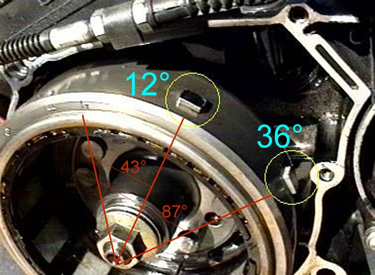
Pickups and reluctors on XT600 before 1990: