
v1r6c1 with WiFi, DAC and Plotter !
This Ignition Timing Meter is extremely valuable in repair work, engine tuning and CDI/TCI testing.
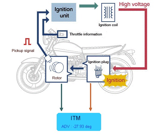
It makes it easy to extract and analyze the advance timing of your ignition box.
It offers an affordable, portable tool used in the field that doesn’t not require a rig or timing lamp to measure the spark angle. For a fraction of the cost of a IGTM-2000
ITM detect the form of the existing crankshaft position pickup and display the type of pickup (Positive first or Negative first) Compatible with one pulse per rev analog pickup coil (VR) and Hall effect sensor.
It calculates and display the RPM.
At the same time, using a Capacitive Probe or a wire winded up around the spark-plug wire, it detects the High Voltage going to the spark.
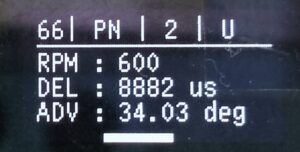
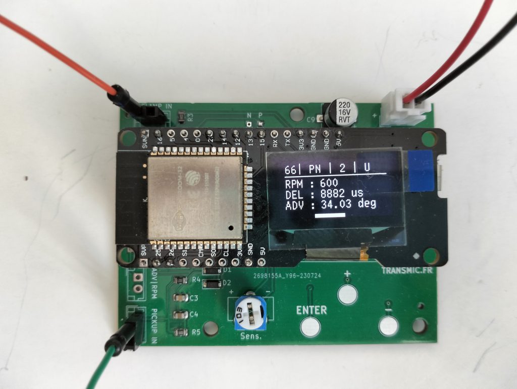
Knowing the pickup time, the spark time and the RPM, the micro-controller then calculates and display the ignition advance timing on an OLED screen.
ITM shows you a highly accurate measure of +/-0.1 degrees
Detect RPM limiter (No Spark detected = no Advance displayed)
Attention! CANNOT test analog CDI like GY6 or my ACCDI v2.8
as there is no processor inside them, just a bunch of resistors and capacitors so the advance timing comes mainly from the voltage of the VR that drift a bit when RPM increases.
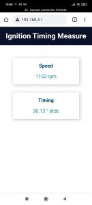
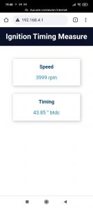
All data are displayed every 1 to 5 seconds (selectable) and available either through Wifi or on a USB connector.
Connect the Ignition Timing Meter to any Windows, Linux, Mac computer throughout a USB connection and terminal console to collect real-time ignition timing measures for further analysis or as a reference for this ignition.
Ignition Timing Meter for CDI/TCI is designed measure timing directly on a running bike only.
It detect the original pickup and detect the spark and then display the timing.
Features
- For 2 or 4 strokes.
- For single cylinder.
- For multiple cylinders if spark detection is captured on cylinder 1.
- Compatible with pickups that put out 1 pulse per revolution (2stk) or per 2 revolutions(4stk).
- Compatible with VR or Hall Effect sensors.
- Does NOT work with missing tooth wheel.
- Input voltage range +/- 3v to +/-35 V.
- Signal conditioning.
- Communication Micro USB Type B Port, at 115.200 Baud 8N1
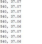
- CSV format (RPM, Advance)
- Compatible Windows, Linux, Mac
- 0.96 Oled 4 lines display.
- WiFi display on any browser @ http://192.168.4.1/console
- 1 Sensor status LED.
- 3 Touch buttons.
- 2 Optional Analog outputs.
- User choices are memorized.
- Power Supply 9 to 16 Vdc 0.1 W
- Internal regulated power supply.
- Dimensions: 72 x 55 x 20 mm/ 2.8 x 2.2 x 0.8 in.
- 3 months warranty
- Weight: 50g / 0.1 lbs
Wifi Display on a Android Phone:
PICKUP.
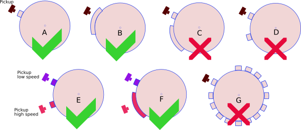
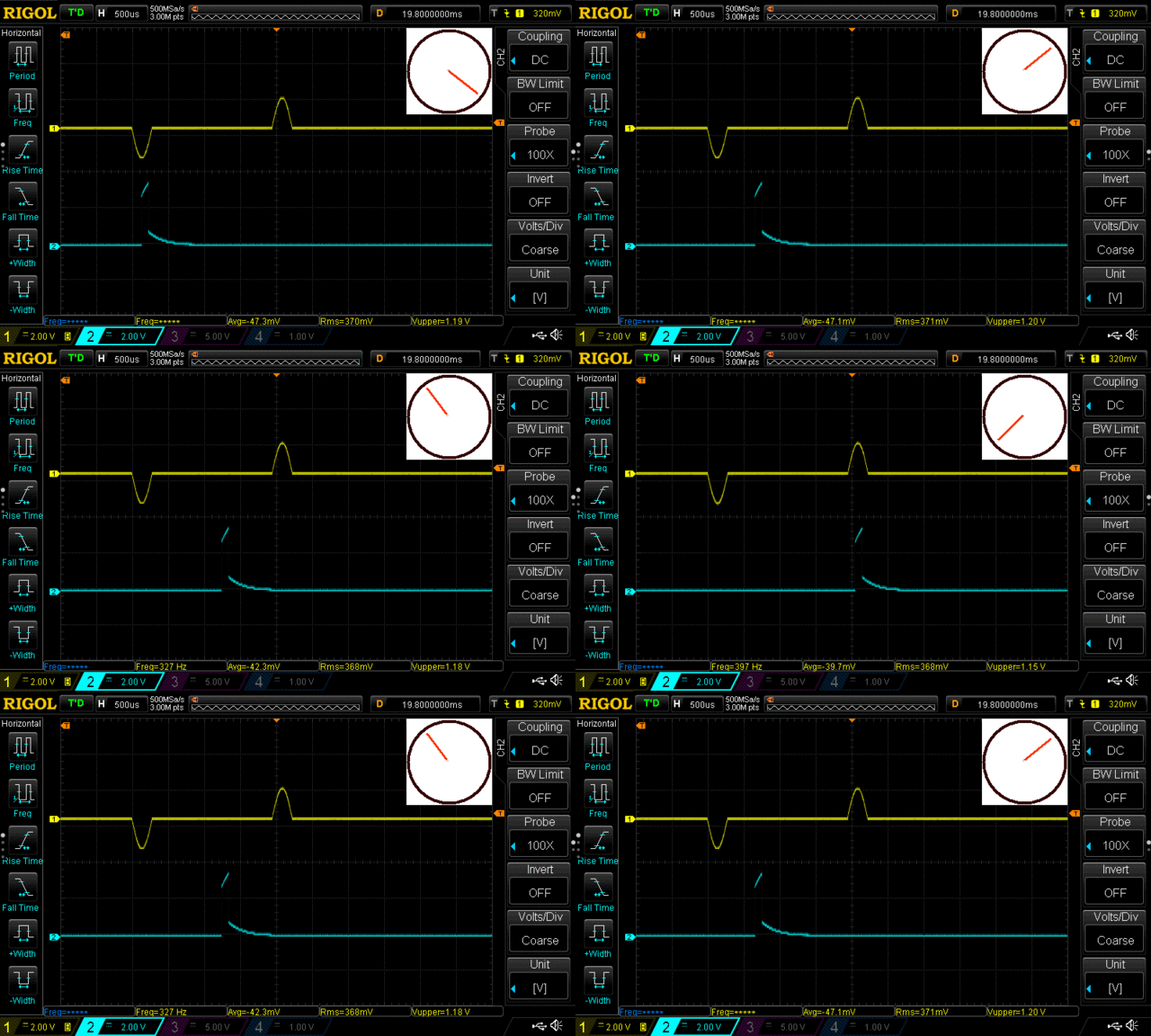
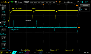
– This ITM works with 1 pickup and 1 reluctor (the metal strip on the flywheel) [A,B].
– This ITM works with 2 pickup and 2 bars [E,F].
– This ITM DOES NOT work with 1 pickup and multi-pulses pickup (ie 2 reluctors on flywheel) [C,D].
– This ITM DOES NOT work with 1 pickup and missing tooth flywheel [G].
Positive first vs Negative first


SPARK DETECTION.
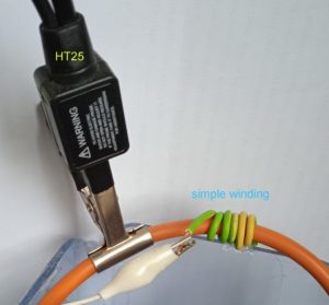
Use an INDUCTIVE probe or just 3 to 10 turns around the sparkplug wire.
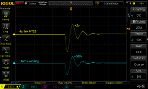
Below the comparison between Capacitive probe HT25 and Inductive probe (wiring): HT25 does NOT work.
/!\ When you are testing an ignition on a bench, replace the sparkplug by a 2k or 5k resistor to cut down electromagnetic interferences that can trouble the device.
So you get rid both of the irritating spark noise and EMI.
WIRING
SETUP
PLOTTER

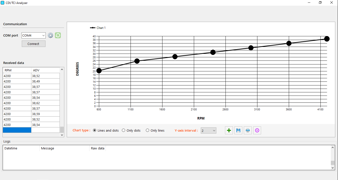
Video: HowTo trace an Advance timing.
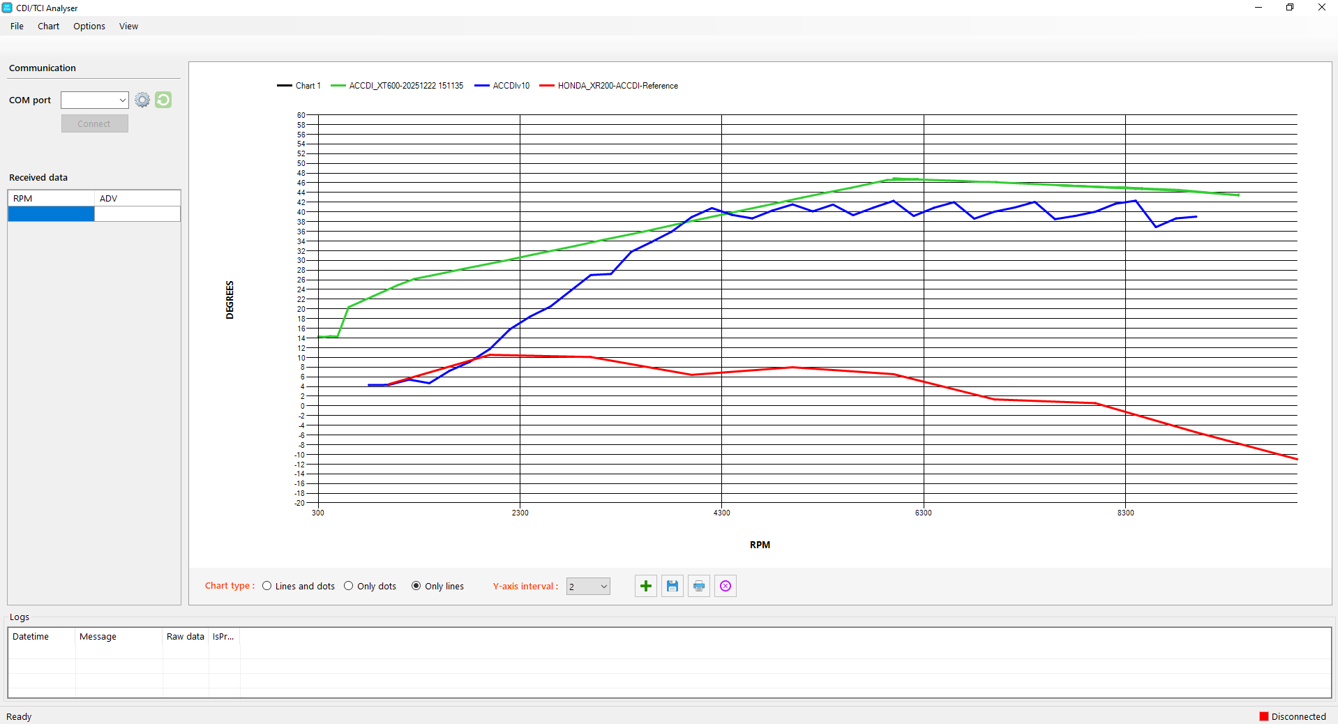
Video: HowTo compare different timing curves.
PHOTOS
VERSIONS
- Version v1r0c0:
- POC
- Version v1r1c0:
- [HW] SMD components.
- Version v1r2c0:
- [HW] Only 2 push buttons.
- [SW] Software Improvement.
- Version v1r3c0:
- [SW] Wifi output.
- Version v1r4c0:
- [HW] Faster processor.
- [HW] Touch Pad instead of buttons.
- [SW] Analog outputs.
- Version v1r5c0:
- [SW] Faster Display.
- [SW] Software Improvements.
- Version v1r6c0:
- [SW] Plotter Software.
- [SW] Software Improvements.
- [HW] 2 colors display.




Hello. I would like a CDI and Tacho meter fornmy 1987 Suzuki DR 600
Would like to have revimiter function on CDi.
Can you help?
Hello,
I have no acces to my database yet and can’t check if there are 2 pickups or only 1
If DR600 has only one metal bar on the flywheel than https://transmic.fr/accdi10/ works.
It has a tacho output on ACCDIv10-T
Hello!
Will it be avaible again?
Thanks, regards.
Luca Del Bene
Hello,
Yes 🙂
I need to improve it a little bit and order some more PCB to the manufacturer.
It should take 1 or 2 months. So during May 2022
Bonjour , votre testeur est il disponible. Cordialement
Bonjour, j’ai reçu 10 circuits mais j’ai encore une modif a tester avant de les remettre en vente..
Je vous préviendrez par PM (si j’oublie pas)
parfait , j’attends votre retour.
I like this very much. It’s a great idea. I have a Matra Murena 2.2 which from the factory in 1980’s was shipped with a crank sensor for electronically measuring ignition timing. It is triggered, however, by two slits in the flywheel so your software would measure double RPM and half the advance, but from your description it should be more or less otherwise plug’n’play. I’d like to offer my help modifying the code, however as I’m a software engineer by education. Would you be interested in that?
I will PM you.
Are they still available? I started building and coding my own design but I would much rather buy yours! Thank you!
Thanks for your interest. This particular one no, but I’m working on a new version (bigger processor, touch pads instead of buttons, Analog output…)
It’s on my workbench, so far so good. 5 should be available end of August.
OFC the price will go up by 20€. Stay in touch.
Not a big fan of touch screens, can’t use them while wearing gloves or when riding a wet dirt bike! 😉 I’m still interested, though!
Do you have a mailing list? Thanks for your reply!
I have version V1R0C0 of this meter. I want to use a Hall sensor for pickup with my DC-CDIv12. The V1R0C0 does not have “P” and “N” pads next to “T1”. Is there a way to hook up a Hall sensor to this version?
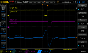
Yes, you can connect directly the Hall Sensor to processor pin D6 for PN or pin D7 for NP
( Input is +5v max ! )
Thank you very much!
Hi,
it will be available again to order it ?
please send me an email when it will be in stock again.
thanks
Christian Piasini
ok
Hello,
please send me an email when it will be in stock again.
many thanks
Joachim
ok
Parfait, j’ai placé ton outil sur mon Suzuki DR750 de 89 au cas ou j’aurais une panne de CDI ( 35 ans)
D’abord paramétré avec position 0, et en signal négatif, il m’affiche un -30 degrés, par ailleurs la RTM indique 5 degrés au ralenti. Donc je le paramétre en position 35 et j’ai bien les valeurs attendues
La courbe enregistrée m’indique une progression linéaire entre 5 et 28 degré, pour respectivement 2200 et 4300 tours
J’ai bien toujours, 5 degré entre 1000 et 2200 ( le ralenti est a 1300 ) en dessous de 1000 il faut placer 0 pour le démarrage
Ah pour info, l’avance de la 2eme bougie qui est sur la 2eme bobine est identique.
Comme ils disent dans les dramas japonais, merci pour ton travail Thierry
Tu fais dans le préventif maintenant ! 🙂
C’est exactement comme cela qu’il fallait proceder. Bien joué Jean-Michel.