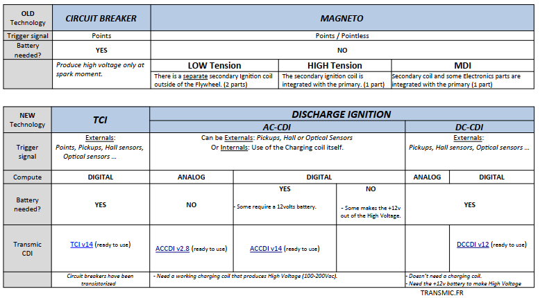
No more OEM? No Problem!
Custom Ignition Solutions for Your Classic Bike!
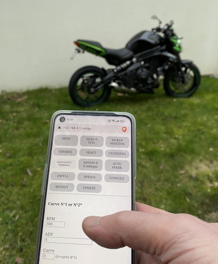
My cutting-edge technology simplifies and speeds up your motorcycle tuning experience!
Just connect your phone to your beloved motorcycle, and you’re good to roll!
Imagine the ease of repair work with a programmable ignition that seamlessly adapts to a variety of bikes.
This is a game-changer for any motorcycle enthusiast, particularly when dealing with discontinued or overpriced original parts.
Making tuning a breeze and ensuring your engine performs at its best.
Programmable DC-CDI.

Features
- Programmable DC-CDI
- Suitable for ONE or TWO* cylinders
- For [2 strokes engines] and for [4 strokes engines with wasted spark*]
* On 4stk engines with a pickup on the crankshaft, one spark occurs during the compression stroke and another during the exhaust stroke.
- Easy programming via WiFi connection.
- You need a simple web browser on any smartphone or laptop. (No app)
- ONE or TWO programmable ignition timing curves. *
- Rev from 10 to 30,000 RPM.
- 0 deg advance from 1 to 500 RPM. (To avoid kickback)
- Adjustable timing in 13 steps from 500 to 20,000RPM.
- Rev limiter.
- 1 input for an inductive pickup (VR).
- 1 input for an Hall Effect Sensor, Optical sensors or Points (An external resistor is required) *
- VR conditioner to extract pickup signal in noisy environment.
- 1 output for a Capacitive coil type.
- 1 input for Kill switch.
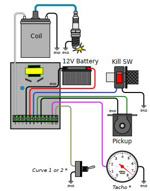
- 1 input to select Timing N°1 or N°2 at startup *
- 1 output for 12v Tachometer signal. *
- 2 settings of High Voltage 150 or 300Volts.
- Power supply voltage DC 6 to 16 volts (For Setup AND to operate).
- Current drain: 100mA – 2A. (Inrush current: 20A/1ms)
- Protected against reverse supply voltage.
- 300V 8A 12pins connector.
- 80MHz MicroController control unit.
- Non volatile configuration.
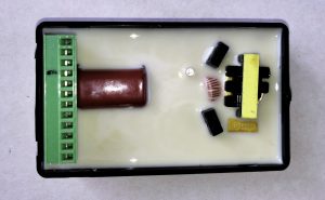
- Dimensions: 100 x 60 x 25mm (3.9 x 2.4 x 1inch)
- Plastic box potted for Electrical insulation, Protecting components from mechanical shock and vibration, thermal shock or Moisture.
- Made in France.
* Options
Cylinders
* Twin-cylinders at 360° crankshaft angle:
The engine works with WASTED spark.
If there is ONE twin coil:
=> This CDI works.
See: CDI compatibility
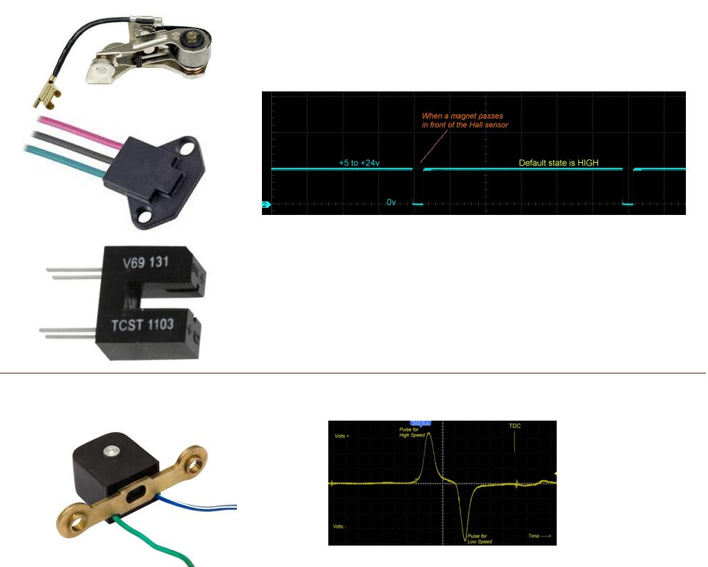
Pickup
It’s made of a coil of wire wrapped around a magnet.
When a ferrous part passes by the magnet, the magnetic field is modified and a voltage pulse is created in the coil generating a sine wave.
DCCDIv12 has:
– 1 input for inductive pickup (VR/pickup coil) with 1 signal per crank revolution. (Pickup must puts out 3 to 100Vac)
– 1 input for Digital sensor (Hall Effect Sensor, Optical sensors even breakerpoints).
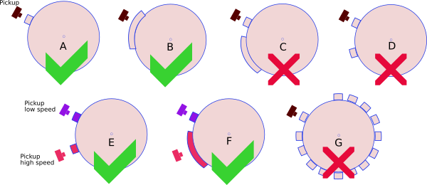
– This CDI works with ONE pulse per rev (1 reluctor only like “A” or “B” below)
– This CDI DOES NOT work with multi-pulses pickup (ie 2 reluctors on flywheel: “C” or “D”).
– This CDI DOES NOT work with a missing tooth flywheel. (“G”)
Pickup Polarity
When the bar/magnet on the stator passes in front of the pickup, the pickup generates two pulses of OPPOSITE polarity.
A pickup has 2 wires.
– If you ground wire number 1, wire number 2 will put out a Positive pulse first when the rising edge comes, then a Negative pulse when the falling edge leaves. I call it PN.
– If you ground wire number 2, wire number 1 will put out a Negative pulse first, then a Positive pulse. I call it NP.
This ignition box works best with Positive first pickup. (VR-PN)
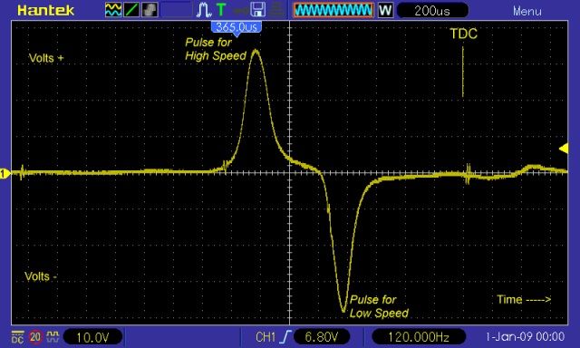
If the polarity is Negative then Positive(NP) then the leads are backward, if possible, just swap the wires to change the pickup polarity !
Watchout! If the pickup is internally grounded and output ONLY one wire, you won’t be able to change the polarity, the pickup output is either PN or NP. You can still use this ignition.
Check the polarity of the pickup: Negative going then Positive/NP or the opposite PN/Positive going then Negative with a Needle galvanometer (in milliAmp position) while kicking.
Pickup Position
“Pickup Position” is the number of degrees between the very first pulse from the pickup and TDC
To be able to provide the largest advance timing (Example 36° @ 4500rpm) the pickup MUST send a trigger signal BEFORE the piston reaches 36° before top dead center (BTDC).
The “Pickup Position” on the Yam XT600 is 50°. Many Yamahas have a “Pickup Position” of 72 degrees.
This “Pickup Position” depends on:
– Where the pickup is mechanically located with respect to TDC?
– Where is the flywheel’s bar located?
– How long is the flywheel’s bar?
“Pickup Position” AKA “Max Advance” = “Base Advance” + “Flywheel’s bar Length”
“Base Advance” value sometime appears is User Manuel.
Length of the flywheel’s bar can be measured this way.
You may measure the “Pickup Position” using a protractor.
or with a caliper and some math.
Pickup Voltage
The higher the RPM, the more voltage it must produce
Formula : Minimum Pickup voltage = RPM/1000 + 3
Example : At 6000rpm the VR pickup must put out : 6000/1000 = 6 + 3 = 9Vpp (Volts peak to peak)
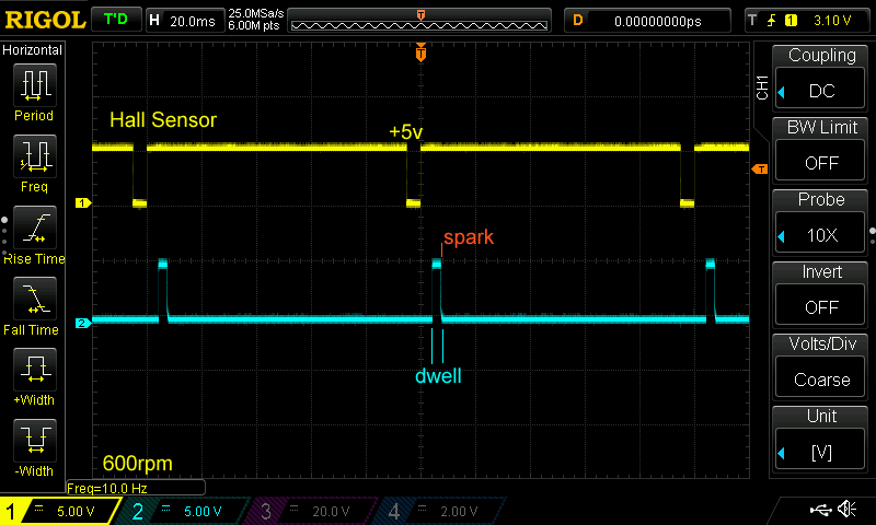
Hall Effect Sensor, Points
– Points, reluctors, Hall sensors, optical sensors can also be used as long as they give only 1 pulse per revolution.
– When a magnet passes in front of the sensor, the output voltage goes low and the ignition will detect the RISING edge meaning the trigger moment will be when the magnet LEAVE the sensor.
– Work with NPN Models : Hamlin 55100, Allegro A1101-A1104, Allegro old 3141-3144, Honeywell 1GT101DC, SS495, SS49E etc…

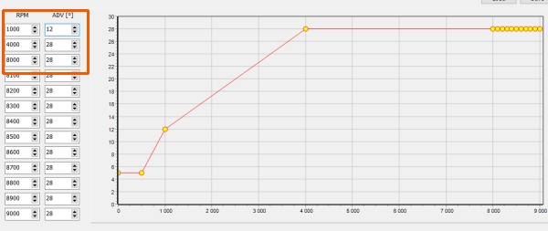
Ignition timing
Windows software: Interactive_Graph.exe
(Extract this software to where it has read/write permission, i.e. in your Document folder)
Tip: No need to use all 13 points if the curve is straightforward.
Just use the first 2 or 3 timing pairs ! The ignition box will process that faster.
Rev Limiter
The last RPM value that has been entered is the “rev limit” that stop all sparks.
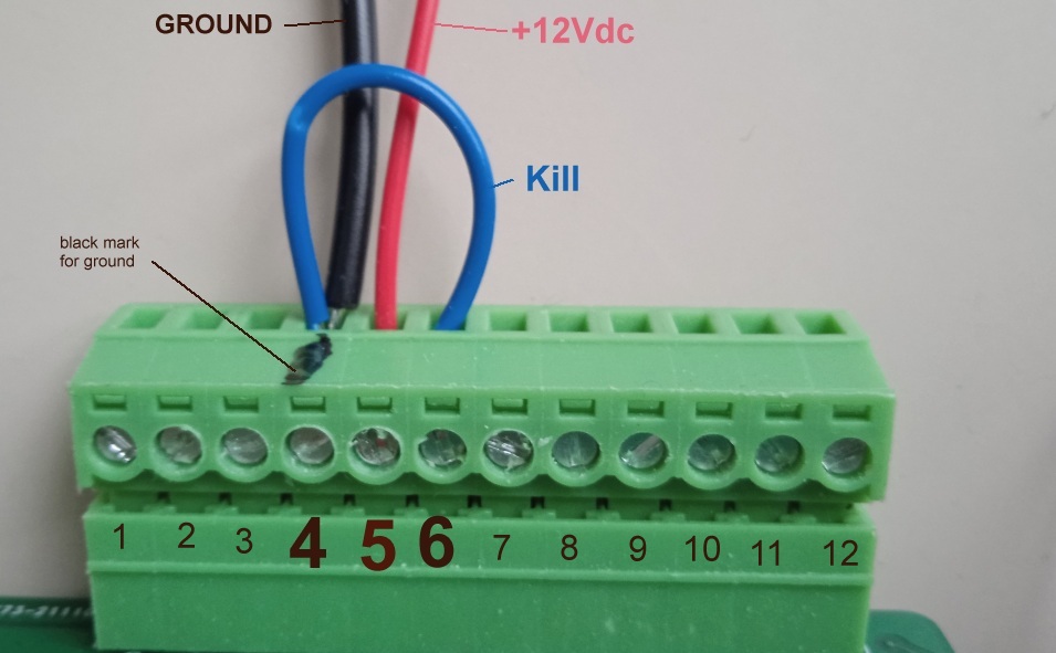
Wiring
Pin 4 is the black mark
HowTo setup
To program the ignition, please Print and follow this procedure: Setup Ignition box.pdf
The 12pins connector has a marker trace on pin4 which is Ground.
1) Connect a Black wire from connector pin4 to the black plug of a 12v battery (minus).
2) Wire a bridge between connector pins 4 and 6 (ground and kill input).
3) Connect a Red wire from connector pin5 to the +12v of the battery (+, red plug) to power up the ignition.
4) Led blinks 5 times while a WiFi Access Point named “Transmic_ign” show up on you laptop/smartphone.
(If a password is asked, use “password”)
Diagnose with LED.
As soon as a pickup signal is detected, led blinks in rhythm.
If the Maximum RPM is reached, the led turns off. If minimum RPM is reached, led turns off.
– If the box starts in SETUP Mode : Led blinks 5 times before flashing once every 5 seconds.
When data arrives via WIFI, led briefly flashes.
Test the whole unit
Remove all connections except the coil and the power line: See video
COIL
CDI ignitions need a CAPACITIVE coil type (AKA Transformer type) for CDI (Not a INDUCTIVE coil for TCI)
Ignition coils are different from TCI to CDI systems.
A CDI ignition can work with a TCI coil but the spark energy will be halved ! Why CDI coils don’t work with TCI ignitions?
– CDI coils have low inductance (L=0.1 to 0.7mH) and primary resistance of around 0.3 to 0.8ohm
– TCI coils have higher inductance (L=4 to 15mH) and primary resistance of around 1 to 5ohm
CDI coils: IMFsoft, Ignitech, FireCore, FuelTech, PW, M&W, Suzuki coil, Kawazaki coil, PVL double coil, Honda double coil,
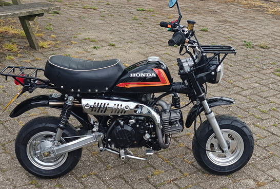
PHOTOS.
Honda Monkey SkyTeam 2009 (with ZS190 engine) + DCCDIv14 :
Legal Eagle XL airplane with half VW engine. Twin cylinder, 4 strokes. 0.5-ohm Buick twin-post coil, MSD wires, Champion plugs, Hall sensor + DCCDIv12:
![]()
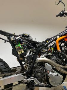
KTM640LC4-1999 (pickup position: 63°BTDC) :
VIDEOS
VERSIONS
- Version v11r8c0:
- POC
- Version v12r1c0:
- Evolution of V11.
- [soft] New menu. User can select strokes and cylinders.
- [soft] 2 timing curves available.
- [hard] 1 switch to select timing curve.
- Version v14r1c0:
- Evolution of V12.
- [soft] New menu.
- [soft] Firmware can be updated.
- Version v14r4c1:
- [soft] Bugs fixes.
- [soft] Timing @500rpm can reach 30°
- [soft] Change Updates server port
Hi, Thierry.
Which type of dc-dc converter will be used?
I am trying to build ignition based on Arduino and little bit stuck with dc-dc converter.
I want to use converter without transformer. Is it possible ?
Hi
It’s a Royer oscillator. https://en.wikipedia.org/wiki/Royer_oscillator
Unfortunately you cannot reach 200v with strong power without transformer!
At 10000rpm you need a very fast load of the capacitor.
Very interested in this is it possible to purchase a complete system for Suzuki intruder vs1400 (1987) and also interested in a complete set up for most inline 4 cylinder bikes?
IMO for a big bore like that TCI is better. DCCDI are for fast small engines.
Suzuki intruder vs1400 is a 45° twin so both cylinders never fire at the same time.
You should need 2 units (2 TCI) or 1 unit specially developed for this bike with 2 outputs.
Would this work on a Kawasaki zx7r?
Features
Suitable for ONE or TWO* cylinders
What do you recommend as the optimum primary coil resistance for this ignition? Engine rpm 2000-4000.
Any capacitive coils for CDI with primary resistance of around 0.3 to 0.8ohm and low inductance (L=0.1 to 0.7mH) Energy = L * I * I so the higher inductance the better.
Do you have any recommendations for spark plug gap? Would you use a larger gap if using 300V output compared to the 150V? I’m guessing 0.025″ for TCI and 0.035″ to 0.045″ for your CDI.
Good question Keith.
IDK. Since it seems rational for CDI to take advantage of the boosted High Voltage to increase the gap. Unless it’ll be too large at start or idle…
For spark plug wires, do you recommend solid, copper core wire, 500 ohms per foot spiral wound resistance wire, or 50 ohms per foot spiral wound resistance wire for your ignition systems?
Although classical solid-core wire would simply work, but since voltage drop is no more a issue with DC-CDI and this ignition generates more EMI, I’d go with a carbon core.
Which resistance? IDK, probably the highest at 500ohm per 30cm
Thank you. MSD spiral wound wire is a popular choice in the USA. Their most popular wire is 500-ohm per foot.
I saw in one of your videos that you used a larger wire gauge for ground and Pin 1 to coil. Is 16 ga wire sufficient for all wiring or do you recommend 14 ga for ground & Pin 1 to coil?
Knowing that current peak can reach 4Amp, I’d use 14ga for + – and coil
Hi there, One question.
What is function about “Auto Spark” in setup menu?
Hi,
Please refer to the Setup.pdf above.
“This autotest function is usable on TCI and DCCDI only.
The ignition box fires the ignition by itself at 300/1000/3000/10000rpm WITHOUT any pickup connected.
This way you can test the wiring, the TCI/DCCDI, the ignition coil and sparkplug”
Does this have the ability to cut Power after the bike has reached the maximum legal speed for a moped 45kmph?
Your question is poorly stated!
A CDI DO NOT know the SPEED ! It knows the RPM only!
If the bike as a gear box, 45km/h equal different rpm if the bike is in 1st,2nd or 5th gear !!
Yes the user can set the MAX RPM this DCCDI can reach. it’s a revlimiter (ie 4500rpm max)
Thanks for your reply, then my plan must become to find a good sprocket ratio for maximizing the possible rpms,
Is it possible to have a sensor to tell the CDI to switch to a different rev limit if it’s in the highest gear?
Or is it possible to add a second circuit that sends a signal to the CDI when maximum speed had been reached?
Would it work to have a MOSFET turning of the supply for the ignition coil when the external circuit senses Overspeed?
I thank you for your time 🙂
You would have to build an external Arduino/ESP based circuit that measure the speed then turn the DCCDI Kill input to ground when it reaches 45km/h
https://www.google.com/search?q=arduino+speedometer
https://www.google.com/search?q=esp8266+speedometer
In the manual it states that “pickup position = base advance + magnet length” What units are used? Because you state base advance in degrees and for magnet lenght you show a ruler. And you don’t have to enter the pick up length anywhere?
This is regarding the dc cdi unit, if that matters.
In degrees OFC.
Look at the ruler: it’s written in degrees if you print one crafted for the diameter of your flywheel.
The pickup length is not relevant. Only the metal bar on the flywheel is.