This TCI v10 is EOL (End Of Live) and has been replaced by a new TCI v11
A programmable ignition is extremely valuable in repair work as it fit a wide array of bikes.
It’s especially helpful if original part has been discontinued or is overpriced.
And of course it is required if you want to tune your engine.
Features
- Programmable TCI.
- For ONE or TWO* cylinders
-
For [2 strokes engines] and for [4 strokes engines with wasted spark*]
* On 4stk engines with 1 pickup on the crankshaft, one spark occur at compression stroke and one at exhaust stroke. Firing in the exhaust stroke is a wasted spark. Hence the name…
- 80MHz MicroController control unit
- Firmware included
- Easy programming with Micro USB Type B connection and terminal console
- Compatible Windows, Android, Mac, Linux
- Non volatile configuration
- One customizable ignition curve
- Engine speed from 10 to 16,000 RPM.
- 0 deg advance from 1 to 500 RPM (to avoid kickback)
- Adjustable timing in 13 steps from 500 to 16,000RPM
- Improve timing curve
- Remove stock Rev limiter
- Legal Temporary rev limiter.
- 1 input for an inductive pickup (VR)
- Can use Hall Effect Sensor or Points (Need external resistor)
- Pickup polarity can be set to Positive, Negative or Automatic detection.
- 1 output for an INDUCTIVE coil type >1.5ohm.
- 1 input for Kill switch.
- 1 output for Tachometer.
- Coil current: Max: 15A
- Coil Over Voltage: Max 430v
- Coil protection: shut off after 2sec if no pickup signal.
- Power supply voltage DC 10 to 16 volts.
- Quiescent current 30mA
- Protected against reverse supply voltage.
- Available as a ready-to-use device in the SHOP section
- Dimensions: 100 x 60 x 25mm (3.9 x 2.4 x 1inch)
- Plastic box potted for Electrical insulation, Protecting components from mechanical shock and vibration, thermal shock or moisture.
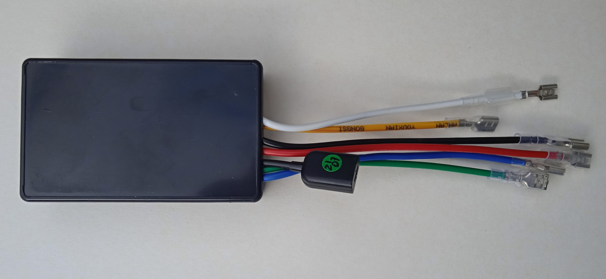
- 15cm(6”) 1.5mm2(16AWG) wires soldered with 6.3mm automotive female connectors.
- Made in France
Cylinders:
Single-cylinder:
If there is one separate pickup:
=> This TCI works.
If there are 2 separate pickups (one for low RPM and one for High RPM):
=> This TCI works and uses only the High RPM pickup.
If the engine works with Missing Teeth:
=> This TCI will NOT works
* Twin-cylinders at 360° crankshaft angle:
The engine works with WASTED spark.
If there is ONE twin coil:
=> This TCI works.
See: TCI compatibility
Remember that ignition coils are different from TCI to CDI systems.
– CDI coils have low inductance and an impedance around 0.5-0.8ohm
– TCI coils have higher inductance and impedance around 1-5ohm
(1ohm for electronic ign. 3ohms for transistorized ign. 5ohms for points ign.)
Pickup:
A pickup (aka: VR, Variable Reluctor, Reluctor) is a sensor that have one signal wire and one ground wire.
It’s made of a coil of wire wrapped around a magnet. When a ferrous part passes by the magnet, the magnetic field is modified and a voltage pulse is created in the coil generating a sine wave.
– 1 input for inductive pickup with 1 signal per crank rev.
– Pickup must put out 3 to 30Vac
– Points, reluctors, Hall sensor, optical sensors can also be used as long as they give only 1 pulse per revolution.
– 3 wires digital Hall effect sensors need an external pull-up resistor. The default voltage output is equal to Vcc (+5v to 24v). When a magnet passes in front of the sensor, the output voltage goes low and the ignition will detect the RISING edge meaning the trigger moment will be when the magnet LEAVE the sensor.
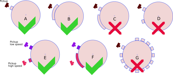
– This TCI works with 1 pickup and 1 reluctor (the metal strip on the flywheel) [A,B].
– This TCI works with 2 pickup and 2 bars [E,F].
– This TCI DOES NOT work with 1 pickup and multi-pulses pickup (ie 2 reluctors on flywheel) [C,D].
– This TCI DOES NOT work with 1 pickup and missing tooth flywheel [G].
Even if it seems instantaneous, the flame front take some time to expand and ignite all the air+fuel mixture in the combustion chamber.
It becomes critical at high rpm. That’s why the ignition box should fire the spark a few degrees before the piston reaches Top Dead Center so the mixture explode just when the piston begin to back up.
Generally engines need to be ignited around 30 to 40° BTDC (Before Top Dead Center)
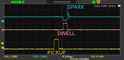
It’s the ignition box job to calculate the timing according to the RPM. It makes the calculation as soon as it detect a pickup signal.
Therefore if the box need to ignite the engine 40° BTDC, the pickup signal MUST trigger the box BEFORE 40° BTDC.
So the pickup position must be at the very least 40° or 42° BTDC.
Due to mechanical constraint, manufacturers put the pickup at different position, Yam XT600 was 36° btdc, Honda often uses 72°…
As the ignition box has been triggered way before it needs to fire the engine, the box just wait until it’s time to fire.
How to calculate the Pickup Position?
- Find the TDC
- Read comment here and there
Pickup Polarity
Check the polarity of the pickup (Negative then Positive/NP or the opposite PN) with a Needle galvanometer (in milliAmp position) while kicking.
For a better understanding, this video can help.
Rev Limiter:
The last RPM value you enter is the “rev limit” that stop all sparks.
Temporary Legal Rev Limiter:
If the Kill switch is switched ON then OFF once during the first 30 seconds after the engine started, a Temporary Rev Limiter will allow 3500RPM maximum for the current run.
After 30 seconds, Kill switch will acts normally and stop the TCI.
After the bike has been stopped and restarted by the Master Ignition Key, the TCI runs without restriction.
In countries where 50cc are strictly restricted, the bike seems lawful in case of control…
It can also be handy if a rookie rider tries the bike.
Ignition timing
– Draw the ignition timing curve into this XLS sheet.
HowTo setup
Terminal console
- Windows
– Use a Terminal Software as CoolTerm or Teraterm or Putty or Kitty . - Android
– Use Serial USB Terminal by Kai Morich and a Male-Male USB type-C OTG connector to USB micro-B. (video)
The phone must be OTG compatible with OTG turned on:
settings——additional settings—–enable/disable OTG. - Mac
– Shell commands:
terminal

ls /dev/*usbserial*

screen /dev/cn.usbserial-xxxxxxxx 115200 -L

screen /dev/tty.usbserial-xxxxxxxx 115200 - Linux
– Use a Terminal Software as CoolTerm or Putty.
– Use Shell commands to find the COM-port:
tail -f /var/log/syslog | grep USB

dmesg | egrep --color 'serial|ttyS'

ls /dev/ttyUSB*
Port Configuration:
sudo su

stty -a </dev/ttyUSB0

stty -F /dev/ttyUSB0 cs8 115200 time 10
Connection to the device:
cat /dev/ttyUSB0 & cat > /dev/ttyUSB0
AutoSpark.
– If “AutoSpark” mode is set to 1 during Setup then once the TCI is powered on, it automatically drives the coil at 600RPM without the need of any pickup.
Useful for test.
Diagnose with LED.
– If the box starts in RUN Mode: Led blinks 1 time then turns off until a pickup is detected.
As soon as a pickup signal is detected, led blinks in rhythm.
If Maximum RPM is reached, led turns off. If minimum RPM is reached, led turns off.
– If the box starts in SETUP Mode : Led blinks 15 times then stays off.
When data arrives through USB, led flashes briefly.
WIRING
Ready-to-use unit: Wiring.
COIL.
Why CDI coils don’t work with TCI ignitions?
LED meaning.
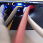
LED in Autospark mode. | LED in Setup Console mode. | LED in Running mode.
PHOTOS.
VIDEOS
Connection to the box:
Setup a ignition timing:
Change the ignition timing:
Extract timing from a TCI:
VERSIONS
- Version v10r0c0:
- POC
- Version v10r1c0:
- [HW] SMD components.
- Version v10r2c0:
- [SW] Add coil protection.
- Version v10r3c0:
- [SW] Populate a default Eprom.
- Version v10r4c0:
- [SW] Add functionalities and fix bugs.
- Version v10r4c7:
- [SW] Add a RPM limiter function.
- [SW] Add AutoSpark function.
- [SW] Setup menu improved.
- [SW] Bug fix.
- [HW] Add external led.

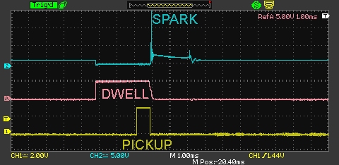
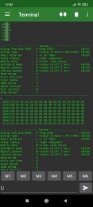
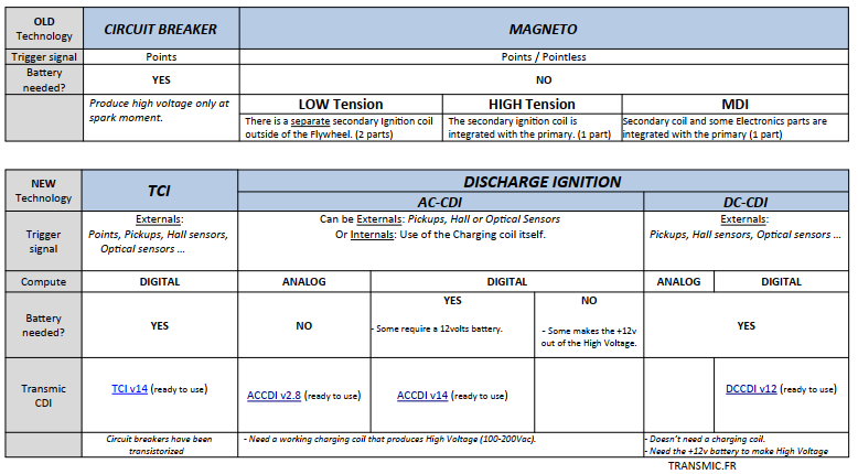
Dear Thiery ,
Do there comes also a version where the schematic and the excel file are on the web , and where it is possible to buy only the software , and and the rest is DIY ?
Thanck you ,
Gerard
Dear Gerard,
That will certainly never happened.
It’s incredible how people undervalue others’s work…
Thierry
Dear Thiery ,
very sorry, but I can understand your decision very well
Best regards ,
Gerard
Dear Thiery ,
I’d like to purchase this item, but it seems to be out of stock.
Could you tell me when it will be possible to purchase one?
thank you.
Rick
Hello Rick,
Thanks for your interest. I had 2 TCI on the workbench to finish. You are boosting me and I’m going to make them available on Friday.
Thierry
Hello Thierry
I noted that 2 type of TCI are available, which one is suitable for Yamaha xt 600 3tb .
How it takes to ship the right TCI?
Thanks in advance.
Stavro
Hello,
One TCI has an external output for electronic tachometer.
Does your bike have a tachometer cable (mechanical) or a tachometer wire that goes to the TCI?
Check that and read the wiring diagram.
There are Yamaha XT600 manuals here: https://www.xt600.de/xt_werkstatt/_technische-referenz/-schaltplan/index.htm
>How it takes to ship the right TCI?
Where to??
I ship parcel on mid-week and it takes 3days to France until 3-4weeks to NewZeland
Th
Ciao Thierry
my bike is equipped with tachometer cable (mechanical) , so please let me know which type of TCI?
Delivery place is Milano, Italy, how will take and cost?
Many tanks for your kindly help.
Regards
Hello
Both works ! But if you don’t need the tacho output, this one is cheaper: https://transmic.net/product/ready-to-use-tci-v10/
it cost 10€; I’m unable to give you a duration of shipping!
French Post don’t give warranty for this 10€ offer. You must pay around 19€ to usually have a warranty, but this time they have stop to give guarantee due to Covid19!
Th
Hello Thierry
I understood that righ type of programmable ignition for my Yamaha xt 600-3tb is TCI-V10, but ready to use means that device is ready for service no need additional set-up, adjustment or programming?
Best regrads.
Stavro Vinjau
Hello Stravro
A plug’n play and programmable TCI would be 5 times this price 🙂
Ready to use mean: All electronic parts and wires are already sold.
You have to:
– connect the wires to your engine.
– setup the TCI (like ANY programmable ignition box!)
Regards,
Thierry
Lets face it: if you don’t know or don’t feel like doing some DIY stuff, consider buying a genuine Yamaha ignition. 😉
HI!
Are you still active?
How complicated is it to set up the ignition box? Where do I find the values for my bike?
With kind regards Ulf Ingelsson
Hi,
setup is described above: HowTo setup > Setup Ignition box v10r3.pdf
>Where do I find the values for my bike?
You need the advance curve: User manual, dealer, forums, measurement: https://transmic.fr/2021/09/23/read-timing-from-flywheel/
and the pickup position, also described above: Pickup section > How to calculate the Pickup Position?
BR
Hi,
I am very pleased to have found your products. What I’m looking for is a unit that can sit between the pickup and the standard ignition / coil and be used to advance the ignition by 2/3 degrees. So I am wondering if you could supply without the CDI part of the circuit and have the output mimic the input pickup.
Thanks in advance.
Hi,
>and have the output mimic the input pickup.
It cannot exactly mimic the signal as the input is an analog pickup (VR) and the output is digital. (0 or 12v)