[ARCHIVE] This ACCDI is EOL (end of live)
Features
- AC-CDI
- For ONE or TWO* cylinders
-
For [2 strokes engines] and for [4 strokes engines with wasted spark*]
* On 4stk engines with 1 pickup on the crankshaft, one spark occur at compression stroke and one at exhaust stroke. Firing in the exhaust stroke is a wasted spark. Hence the name…
- Microprocessor control unit
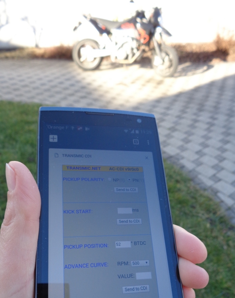
- Wireless and easy programming and the fly via smartphone or laptop
- Compatible Android, IPhone. Windows, Linux
- Programming security:
- Only possible when engine is stopped.
- Only possible when ignition key is ON.
- One programmable ignition curve
- Rev from 200 to 20,000 RPM
- Adjustable timing in 10 steps from 1000 to 10,000RPM
- Adjustable timing at very low RPM (~250RPM)
- Soft rev limiter.
- 1 input for a inductive pickup
- Selectable pickup polarity (2 types)
- 1 output for a capacitive coil type
- Non volatile configuration
- Tachometer output
- Kill switch
- Power supply voltage DC 8 to 16 volts
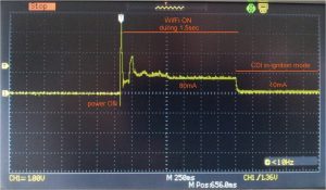
- Current drain: 10mA in Ignition mode (80mA during Wifi mode)
- Protected against reverse supply voltage
- Dimensions: 80 x 55 x 34mm (3.2×2.2×1.3inch)
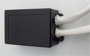
- Plastic box
- Made in France
- Only available in the SHOP section
- Source and hardware not available
Cylinders:
Single-cylinder:
If there is one separate pickup
=> This AC-CDI works.
If there are 2 separate pickups (one for low RPM and one for High RPM)
=> This AC-CDI works.
If there is no separate pickup and the timing is done by using the High Voltage of the stator
=> This AC-CDI will not works
If the engine works with missing teeth
=> This AC-CDI will not works
* Twin-cylinders:
If the engine works with WASTED spark and if there is ONE twin coil.
=> This AC-CDI should works.
If the twin engine doesn’t support wasted spark:
=> This AC-CDI will not work
See: CDI compatibility
Remember that ignition coils are different from TCI to CDI system
– CDI coils have low inductance and impedance around 0.5-0.8ohm
– TCI coils have higher inductance and impedance around 1-3ohm
Remember there are AC-CDI and DC-CDI…
Pickup:
– 1 input for inductive pickup with 1 signal per crank rev.
or for 1 inductive pickup with separate output for low and high rpm (XT600)
– Pickup must give 2 to 30Vac
– Points, reluctors, Hall sensor, optical sensors can be used as long as they give only 1 pulse per revolution.
– CDI is not compatible with multi-pulses pickup or missing tooth wheel.
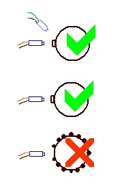
– input for low pickup if any.
– Jumper JP1 can be choose to help cranking:
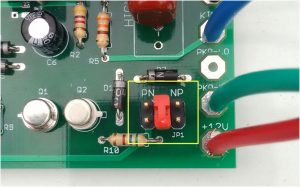
- Jumper on PN position if the pickup is POS/NEG (ie Yamaha)
- Jumper on the middle position : Default position: No help at cranking.
- Jumper on NP position if the pickup is NEG/POS (ie Suzuki)
Pickup position BTDC
Understand the pickup setting.
Rev Limiter:
There is no “Hard rev limiter” that stop all sparks above a given RPM
but you can drop the timing back far at high end so the engine cannot rev more.
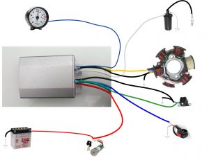
Wiring:
WIRELESS Setup:
To proceed to the initial setup
- First connect the wiring of the AC-CDI
- Turn the Kill SW on. (Kill wire connected to Ground)
- Next turn the Master Key on (+12Vdc)
- After earing a bip sound from the CDI, seek for “transmic_cdi” wifi network on your smartphone.
- Connect to the Wifi Access Point (no password needed)
- Open up a regular browser. Point it to https://transmic.cdi or http://192.168.4.1
- You get this home page:
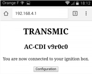
- Click on the Configuration button and follow this video:
Wireless Setup - When finish turn the Kill SW and the master key off.
NB: Each time you log on the CDI the form display a pickup position of 52° which is the default value, but not the value you had previously entered.
Troubleshoot with LEDs:
In CDI mode, with KILL SWitch not connected to GROUND:
Red led blink 3 times then both led are OFF => CDI is in ignition mode.(default mode)
Videos: mode_CDI mode_CDI_slowmotion
In Access Point mode for wifi programming, when Kill switch is connected to GROUND prior to turn the master key ON:
– Red led blink 3 times
– Buzzer ring
– Red and Blue led are steady ON. => CDI is in Programming mode
– After 5 seconds, buzzer ring => CDI is ready to be programmed
Videos: mode_AP mode_AP_slowmotion
The Blue LED turns off during Wifi communication with the processor.
Kickstart Setting:
it’s the length of time the cdi box will retard the timing for anything under 500rpm.
Values are around 15 to 30ms. You can use this Excel sheet to calculate how much advance it would give at crank speed.
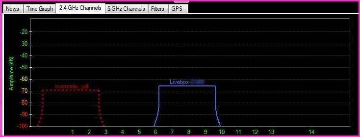
WIFI range:
10 meters distance from the CDI (compared to a regular ISP box at same distance):
Consumption:
Version 9.3 has drastically reduce the current needed in CDI mode.
Only 10mA and 14mA with sparks. Can be powered on with a simple 9v battery cell.
BOX:
VERSIONS
- Version 9.0:
- First Version.
- Version 9.1:
- [Hard] Less components, lower price.
- [Soft] Blue LED blink during wifi communication as a feedback.
- Version 9.3:
- [Hard] Plastic box for better wifi. Use SMD parts for smaller PCB
- [Soft] Consumption divided by 6 ! Can now be powered by a 9v battery.

Nice … was thinking of doing something on similar lines. Great. All the best.
What is the maximum number of cylinders it can handle?
Version v9.0.0 is designed for 1 cylinder.
It should work on a Twin-cylinders if the engine works with WASTED spark and if there is ONLY ONE twin coil.
ie: It works on BMW as they are opposed twin/4 strokes, and needs only one spark every 360°, the very same as a single cylinder/2 strokes.
Their twin coil has 2 outputs and fires the 2 sparkplug at the same time.
(One spark is wasted as one cylinder is on its exhaust stroke.)
See left part of this animation.
As you mention the ignition can handle wasted spark, I supposed it then can work for a three-cylinder engine with wasted spark and three ignition coils firing in paralell, that gives one real spark for ignition + two wasted sparks per revolution for each cylinder.
For example a three-cylinder engine that revs 8000 rpm, the ignition need to produce 3×8000= 24 000 sparks/min, or 400 Hz.
What is the maximum sparks/min the v9 ignition can produce?
You are right. It could theoricaly work… but there are 2 limitations: hardware and software
Hardware :
The CDI has one output meaning that it can drive:
– one coil: fit 1 cyl
– one twin-coil: fit 2 cyl
– 2 coils in parallel: fit 2 cyl
– a distributor to fit 4-8 cyl
if you drive 3 coils in parallel , their low impedance will be divided by 3 and can destroy the output SCR inside the CDI
It also mean there are wasted spark during intake and exhaust strokes inside the 2 others cyl.
Software:
Without wasted sparks:
Number of sparks = ( RPM x cylinders ) / 2
ex: 3000rpm on twin cylinders: 3000 x 4 /2 = 6000 sparks / minute = 6000 /60 = 100Hz
With wasted sparks:
number of sparks = ( RPM x cylinders )
ex: 3000rpm on twin cylinders: 3000 x 4 = 12000 sparks / minute = 12000 /60 = 200Hz
AC-CDI v9.0.0 can reach 400Hz but the RPM range that is adjustable is 500 to 10000RPM (then 250 to 5000 on a twin)
Sorry I was unclear about my example about the three cylinder engine!
I was referring to a two-stroke engine, that ignite the fuel every revolution. My intention was to use the CDI on a two-stroke engine.
Ok, so essential you are saying that the ignition can handle 400 Hz, but the possible problem with three paralell coils would be the low resulting impedance from them, affecting the SCR!
– Would it work then if the three coils are in series instead (at 400 Hz), that means adding 3 times impedance, compared to a single coil impedance?
– If I understand you right the adjustable part of the curve is from 250-5000 rpm if useing the CDI on a two-stroke (without wasted spark). But it will give sparks up to 10000 rpm for a single cylinder two-stroke engine, and sparks up to 20000 rpm for a single four-stroke engine.
– Is it only a programming issue that make the max limit to 5000 rpm for one spark on every engine revolution, or is it the processor speed that are the limitation?
– Do you have any possibility to make an alternative PIC-programming for a two-stroke application?
To drive 3 coils your need a CDI with 3 outputs. That’s it!
Otherwise serial or parallel are just compromises…
Parallel (high current) is a threat for the SCR depending on its characteristics and need a bigger cap
Serial (lower current but lower tension) is poorer performances.
I don’t have experience with 2 stroke as there are rare.
As I understand it, RPM is divided by 2 for a twin 4 strokes (useful spark each 2 crank rotations) but is not for a twin 2 strokes (useful spark each 1 crank rotation) so this CDI “should” perf the same (adjust until 10,000 and capable of 20,000)
If your current CDI works, why don’t you check that on yours?
Plug a scope on each sparkplug and on the main pickup and do the math.
it’s software limitation for the most part. Processor speed only limit the accuracy at high RPM
This coming AC-CDI is intend to be sold only 😉
I realize I talked about a 2cyl-2stk, not a 3cyl-2stk then forget my answer…
You really need to sort that out first before considering buying this CDI.
Will the system work with a Hall-effect pickup for a trigger? Can you recommend coils that would work best?
Yes. This CDI can be driven by points, reluctor, hall sensors, optical sensors as long as there is only one pulse per rotation.
see: http://www.molla.org/DIY-CDI/DIY-CDI-Trigger/DIY-CDI-Trigger_Fig03s.jpg
I don’t have any hall sensor reference to suggest. Choose one for automotive with better temp. and vibration prone characteristics.
This DRV5013 from Texas seem nice.
Can I get the Schematic and PCB designs for this V9?
How to filter noises on rx pins? Because This noises can confuse The microcontroller.
Wireless Programming is only possible when engine is stopped. So there is no EMI noise owing to sparks.
hello,
when version 9 will be available on the shop?
Thanks for your interest !
It’s plan to be available this month March2018.
At the same time I change the whole site look.
BR
The v9 cdi. Would it work on a dr600. How easy would it be to set up ect. Thanks.
According to https://transmic.net/2016/07/19/ac-cdi-suzuki-dr600/ DR600 has one pickup at 0deg (grey wire) for cranking and another pickup at 30deg (green wire) for rev.
I would try first to close jumper JP2 in order to use the positive signal to help starting.
And if I get any kickback I would connect the Low pickup (Grey wire) to the pickup12 input available on the board.
The v9 cdi Would it work on aprilia rs-125 Rotax 123?
Please check the bike manual.
Aprilia 122 is a 2strokes Rotax engine with AC-CDI and 1 trigger coil.
ignition view
So it should work.
If not, send it me back during the 30days warranty.
(warranty does not cover the port fees)
Hi,
wil it work for a Honda CB450S (PC17)?
Wastet spark iscommon for this bike.
2
Hi,
This bike seem to be a twin with 2 points , mechanical advance system and one ignition coils with 2 outputs
http://www.amotorcyclenut.com/honda-350-450-twin-ignition-timing-advance-unit/
No it won’t work.
BR
@Headlee: I can’t answer your email (wrong addr).
According to Google Beta 300RR is a 2strokes single cylinder with AC-CDI
Well …“Kokusan AC-CDI” doesn’t help a lot, like “Dell laptop” don’t give informations about the PC.
This AC-CDI v9 can be used as replacement on any single cylinder equipped with AC-CDI that has a separate pickup giving ONE pulse per rotation.
The AC-CDI v9 must be powered by a 12volts battery
Does your bike fit this requirements?
Single cylinder: OK
AC-CDI: OK
External 12v battery: ?
External pickup: ?
Look at the electrical scheme in your engine manual to see if the CDI use a separate pickup.
In 90% of the case, it does.
Your AC-CDI must have at least 5 wires:
GND
+12v
charging coil
Pickup coil
kill switch
I think it should work, If not send it me back before 3months for a 79€ refund via your Paypal address.
AC-CDI v9 has only one map.
The unique advance curve can be tuned wireless.
No dedicated app is needed thanks to the usage of any regular browser. (html page)
Th
Hi!
Could your cdi kit used for husaberg 2003 650?
What else would be needed and modified?
Thanks,
Toni
Husaberg 2003 and before used a SEM ignition (the same as KTM).
It’s a pure analogic CDI and doesn’t have a separate pickup => this AC-CDI v9 will not work
Husaberg 2004 and after used a KOKUSAN ignition that have a separate pickup => this AC-CDI v9 should work
electrical wiring:
http://photobucket.com/gallery/user/eferm/media/bWVkaWFJZDozMDc3ODA5OQ==/
Hi,
Does it have input for TPS?
Regards
Bikram
Hi Bikram,
There is no input for TPS because it’s a 2D curve, not a 3D.
Regards
Th
Hi Thierry,
Yamaha SRX-600 1985-1987 is very similar to Yamaha XT600 etc –
brown wire and red wire for ignition energy
white-red, white-green and green for pick-up
according to the workshop manual, ignition timing is 12 degrees from 0 to 2000rpm, ramps to 34 degrees at 4000rpm and higher
No electric start on SRX600….
Your AC-CDI V9 uses only the first pick-up signal, right?
And there’s no way of knowing if the engine is at TDC-firing or TDC non-firing stroke, so you always fire a spark at both firing point and at end-of-exhaust-start-of-intake…. right?
From https://transmic.net/2016/07/14/yamaha/, if I understand right, I think that the standard CDI works like this –
at low engine speed, ignition is fired on the second (negative) pick-up
there is another bit of circuitry (analogue frequency-to-voltage) that creates a discharge of the capacitor, delayed after the first (positive) trigger….
below around 2000rpm, this delayed discharge happens after the second (negative) pick-up has already fired the spark, so nothing happens
as engine speed rises, the delay gets shorter… above around 2000rpm, this discharge happens before the second (negative) pick-up, so it fires the spark. When the second (negative) pick-up “fires”, it does nothing because the capacitor is already discharged
above about 4000rpm, the analogue delay is effectively zero, so the spark fires on the first (positive) pick-up
Is this the correct understanding?
So how does the AC-CDI V9 time the sparks?
Obviously, you use the time between first pick-up pulses to calculate the engine speed…. and then look up from the programmed graph what the spark timing should be…
So – do you time from the pick-up all the way to around 360 crank degrees later?
on SRX-600, first pick-up is at 34 degrees….
so to fire spark at 40 degrees, fire it 354 degrees after the pick-up
and to fire the spark at 10 degrees, fire it 384 after the pick-up
BUT during kick-starting, you can’t calculate the engine speed because it’s only one or two engine revolutions – so you fire the spark on the pick-up… right? So could be difficult to start without kick-back…
So, can I do this ?
connect to the second pick-up (wire back-to-front to make it appear positive….)
have spark fired at the pick-up during kickstarting
have an offset of ~22 degrees in my spark map…
cheers
Thom
Hi Thom,
Thanks for your interrest and for the infos about SRX.
So a lot of questions there!
>your AC-CDI V9 uses only the first pick-up signal, right?
No it can use both first and second pickup signal too:
The “idle” pickup that fire the SCR immediately
+
The “high rev” pickup that fire the processor and goes toward the curve
>And there’s no way of knowing if the engine is at TDC-firing or TDC non-firing stroke,
For sure !
> so you always fire a spark at both firing point and at end-of-exhaust-start-of-intake…. right?
Right, it’s called “wasted spark system”
>at low engine speed, ignition is fired on the second (negative) pick-up
Right , but it does not use absolutely the (negative) signal! I don’t know if Yamaha’s cdi use the neg or the pos. but I use the positive signal or the second/idle pickup on mine
>below around 2000rpm, this delayed discharge happens after the second (negative) pick-up has already fired the spark, so nothing happens
Right
On Yamaha: I don’t know exactly if the first pickup (high rev) is not use at all below 2000 as it is not detected by the CDI (signal too small) or if it trigger a spark AFTER the one sent by the idle pickup
On mine: Totally! “this delayed discharge happens after the second (POSITIVE) pick-up has already fired the spark, so nothing happens”
>as engine speed rises, the delay gets shorter… above around 2000rpm, this discharge happens before the second (negative) pick-up, so it fires the spark.
Exact
>When the second (negative) pick-up “fires”, it does nothing because the capacitor is already discharged
Still discharged or not is not the point, the key is: a second spark during explosion stroke does nothing
>above about 4000rpm, the analogue delay is effectively zero, so the spark fires on the first (positive) pick-up
yes
>So how does the AC-CDI V9 time the sparks?
>Obviously, you use the time between first pick-up pulses to calculate the engine speed….
Right
> and then look up from the programmed graph what the spark timing should be…
right
>So – do you time from the pick-up all the way to around 360 crank degrees later?
No. The processor use the time between the 2 last pickups, those from the revolution before.
>on SRX-600, first pick-up is at 34 degrees….
>so to fire spark at 40 degrees, fire it 354 degrees after the pick-up
> and to fire the spark at 10 degrees, fire it 384 after the pick-up
No, on XT600 the pickup is localized at around 38-40 deg btdc to spark at 34
They setup the pickup slightly BEFORE the max advance needed.
>BUT during kick-starting, you can’t calculate the engine speed because it’s only one or two engine revolutions
Exact
> so you fire the spark on the pick-up… right? So could be difficult to start without kick-back…
No that where the “kick start” value come at play. It’s a number of milliseconds to wait before sending the very first spark. It’s tunable by the customer
Make sense?
regards
Thierry P
Hi Thierry,
sorry, a couple more questions!
I watched the video how to program the unit via wireless – and I looked at the picture of the populated board
1) if you connect 2 pickups (like XT600. SRX600 etc), how do you program the unit to know there are 2 pick-ups?
or is it like this –
PKP12 pickup always fires spark immediately (fixed milliseconds delay after 12-degree pickup…?)
PKP36 pickup uses the programmed table for spark timing
2) if only one pick-up connected,, connect to PKP36 pin on board, and unit knows no pick-up connected to PKP12, so during stating fires spark at fixed millisecond delay after PKP36 pick-up….. right?
3) the table of spark timing vs engine speed….
does it do linear interpolation between break-points, e.g.
500 12
1000 12
2000 12
3000 24
etc…
so at 2500rpm, do you get 18 degrees spark timing, or still 12 degrees…?
4) can you change the speed break-points?
Hi, I have a 1991 XT600E with TCI. Ignitor is a NIppon Denso 184-276 ohm pickup and coil is pri 3.4-4.6 ohm to step up to 10.4-15.6k ohm. Will your unit work with this? Cheers
Hi
No. As written in the FAQ, TCI is not CDI
I am very interested in your ignition could you please send me a email I will like to buy two pieces
Peter
Kencevski
Hi Peter,
thanks you for your interrest in it.
You can find it in the SHOP Section here: https://transmic.net/product/ready-to-use-ac-cdi-v9/
I’m going out of stock very soon, so don’t worry if you see it unavailable for 2 weeks…
The time needed for building a few…
Regards
Thierry
Hi. Send me your email please.
Hi, There is a link “Contact us” on the top menu.
Hi,
This is a great project.
I have yamaha 350( RD)…
It has a custome magneto assy ..
It works in following method…
Simple i explain…
In magnet there is 2 north pole 2 south pole. North pole job is to positive charge. South pole job is nagative discharge. One North & south fire @ 12 o clock & another North &South fire @ 12. 30. So what we understand here 2 cylinder 2 timing.
Can i yse this ac cdi on my rd…
Hi,
I don’t think it’s possible, let me get some more technical info from http://www.rd350lc.net/
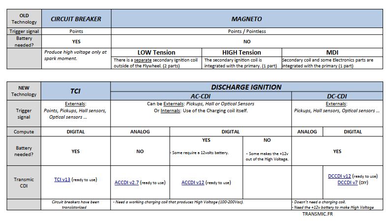
There are 3 families of ignitions :
– Don’t need a battery
– Produce high voltage only at spark moment.
– Need a battery
– Produce high voltage only at spark moment.
Years after, electronic came in with « Electronic Ignitions »
TCI
Circuit breakers have been transistorized (Transistors replace the points.)
then
AC-CDI
– Need a charging coil that produce High Voltage permanently.
– Don’t need battery
DC-CDI
– Doesn’t need a charging coil.
– Use the +12v battery instead to produce HV permanently.
This CDI is a AC-CDI and cannot replace a MAGNETO system.
Can I get the Schematic and PCB designs for this V9?
Sorry, Source code schematic and hardware are not available.
It’s only on sale.
Thank you for a reply!
I decide to wait for the arrival of the product.
Hello
My motorcycle have a DC CDI.
Is it possible to put this AC CDI with a new wiring?
Thanks
Hi,
Of course not!
The bike has a DC-CDI because it has no High Voltage AC source coil. (Only LowVoltage AC for charging the 12 battery)
No AC = No AC-CDI possible.
BR
Good Afternoon,
In the manual of my bike, it’s written that there is a ac cdi but all aftermarket cdi I found for it are dc cdi.
How is it possible?
I’m not a big connoisseur of electricity abd I’m a little lost.
Hello again
I have an answer from a person who know my model better than me “technically it utilises a combination of 12v dc and low voltage ac,as opposed to the earlier analog CDI units which use high voltage ac only”.
Will your V9 work?
It’s unclear but it seem you have a DC-CDI (powered by +12v battery)
This one v9 is AC-CDI not DC-CDI so it wont work.
Hi Thierry, should we expect arrival of this product in stock in near future?
Thanks Eugene for your interest,
Yes, I’m in the process of building 10 of them. There should be available around the 8th of July.
I would like to buy as I do
Thanks for your interest into this product.
I’m sorry but I have stopped the production as I’m currently working on a new ACCDI v10 more accurate. The difference is that v10 will be programmable via USB cable. (no wifi)
The price will be equal or less then v9
Regards
Th