

TM11-03 – 101 407 00
2 strokes:
Aprilia 125 RS,RX,MX,Tuareg, Pegaso (1989-1993)
TM11-08 – 101 855 00
2 strokes
TM11-09 – 101 407 01
KTM 440 SX/MXC/EXC (1994)
TM11-10 – 102 032 00
Husqvarna TE (350,410,510,610) (1983-1994)
TM13-02 – 101 770 00
TM13-03 – 102 074 01
TM14-01 – 101 815 00
2 strokes
Aprilia 125 RS,RX,MX,Tuareg,Pegaso (1993-1997)
TM14-02 – 101 830 00
TM14-04 – 101 888 00
2 strokes:
250 EXC, EGS (1988-1991)

300 EXC, EGS, MXC ,SX (1990-1991)

360 EXC, EGS, MXC ,SX (1996-1997)

380 EXC, EGS (1998-1999)

Aprilia 125 RS,RX,MX,Tuareg,Pegaso,AF1 (1989-1998)
TM14-05 – 101 890 00
4 strokes:
350 LC4 EGS (1993), 350 LC4 EXC (1993-1994), 350 LC4 SC Super Competition (1994-1995)

400 LC4 Duke (1994-1995), 400 LC4 EGS (1993-1997), 400 LC4 EXC (1993-1996), 400 LC4 RXC (1994-1996), 400 LC4 SC Super Competition (1995-1998), 400 LC4 SX (1998), 400 LC4 SXC (1997-2000)

500 LC4 EGS (1988-1992), 500 LC4 EXC (1988-1989), 500 LC4 MX (1988-1989)

540 LC4 SXC (1998-1999)

600 LC4 EGS (1988-1993), 600 LC4 EXC (1988-1993), 600 LC4 MX (1987-1992)

620 LC4 Competition (1997-1999), 620 LC4 Duke (1994-1995), 620 LC4 EGS (1994-1996), 620 LC4 EXC (1994-1995), 620 LC4 Rally (1994-1997), 620 LC4 RXC (1994-1996), 620 LC4 SC Super Competition (1995-1998), 620 LC4 Supermoto (1998-1999), 620 LC4 SX (1994-1999), 620 LC4 SXC (1997)

640 LC4 Rally (1997)

660 LC4 Rally (1997)

Husaberg FE FC MX 350 400 501 600 - 1991 to 1998

Husqvarna TC TE WMX WXE 350 610 - 1990 to 1994

Husqvarna TC TE TX WMX 510 - 1987 to 1990

Vor 535 MX

Vertemati All models
TM14-06 – 101 894 00
2 strokes:
125, 250, 300, 360, 380 MX GS SX (1990)
TM14-07 – 101 888 01
2 strokes:
250 EGS,Enduro (1997-1998)

300 EGS,SX,Enduro (1996-1998)

360 EGS (1996-1997)

380 EGS (1998)
TM14-04 is exactly the same as TM14-07 (same advance circuit, only the PCB has been changed)
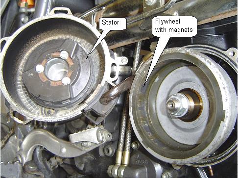
FLYWHEEL and STATOR
On the right side of the bike.
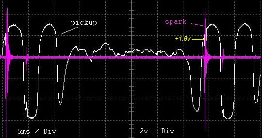
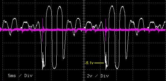
Oscillogram
| red | charging coil = 200Vac |
| green | pickup coil = +/-6Vac |
| black | frame ground |
| yellow | lighting coil |
| blue | lighting coil |
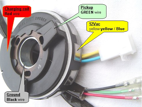
Click on wire above to visualize the signal available on this wire, when the engine idles…
Inside the stator
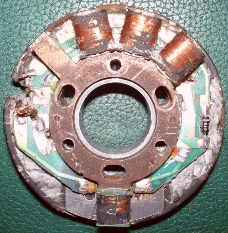
Thanks to Zoli Bihari
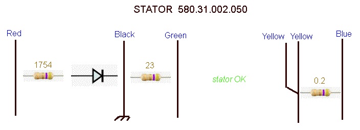
STATOR
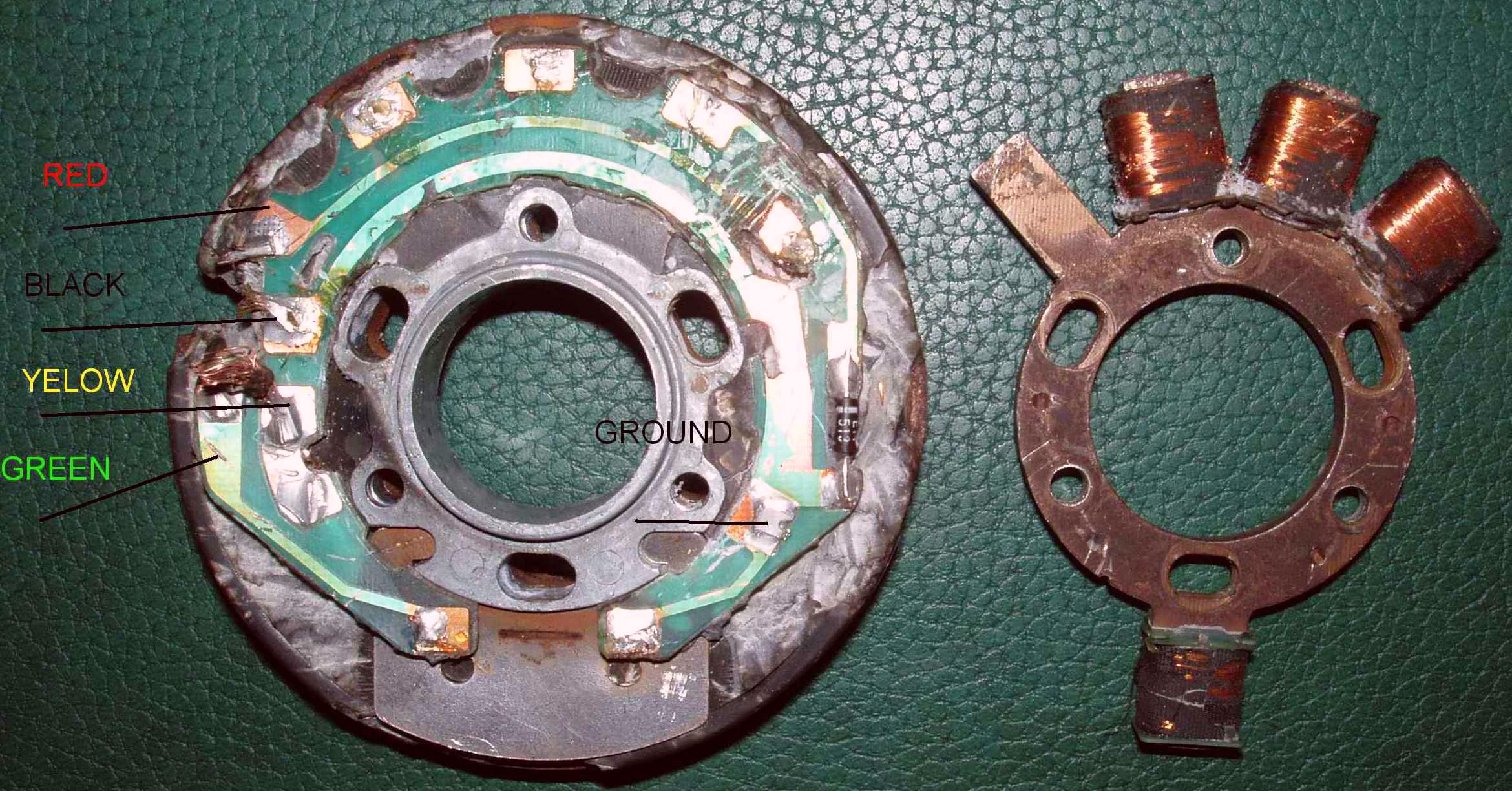
Resistances map on stator side, CDI disconnected.
| OHMs | Red | green | black | yellow | blue |
| red | 1777 * | 1754 * | OL = infinite | infinite | |
| green | 500-1777 * | 23 ** | infinite | infinite | |
| black | 1754 * | 23 ** | infinite | infinite | |
| yellow | OL=infinite | infinite | infinite | 0,2 | |
| blue | infinite | infinite | infinite | 0,2 |
* There is a pre-rectifier internal diode in series, so ohm readout changes on where is the +probe.
** Until 1998 pickup coil (green – black) was 23ohm. After it’s 165ohm.
CDI disconnected, while kicking Red gives 30-50V and Green: 3-5v.
Here is how STATOR looks like when measuring connectivity, resistance and capacitance between wires:
CDI and IGNITION COIL
It’s not a simple coil!
CDI and coil have been put together; we can see the back of the PCB of the CDI:
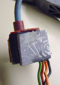
| red wire | charging coil = 200Vac |
| green wire | pickup coil = +/-6Vac |
| black wire | frame ground |
| orange wire | handelbar kill switch |
Here is how COIL/CDI looks like when measuring connectivity , resistance and capacitance between wires:
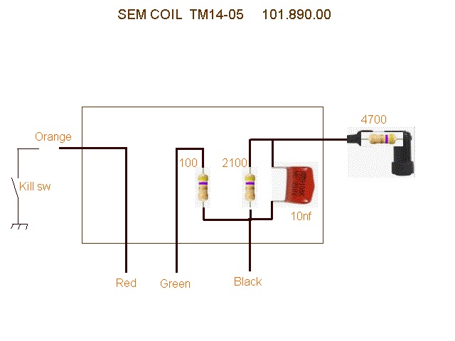
SCHEMATIC
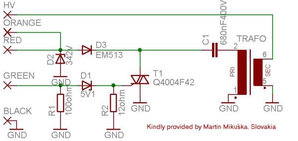 Orange “BLACK BOX” from a KTM 620LC4 – 1997
TIMING
- Pickup and Spark Signal at 1460RPM.
- Pickup and Spark Signal at 2880RPM.
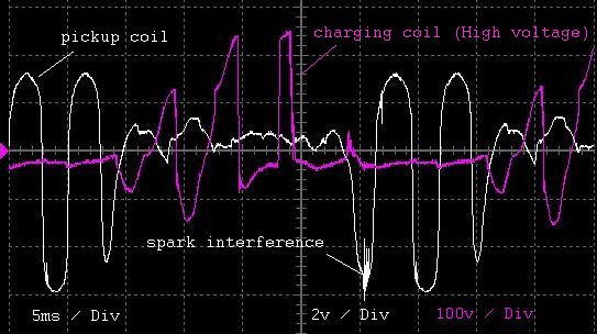
- Pickup and Charge voltage at 1770RPM.
-
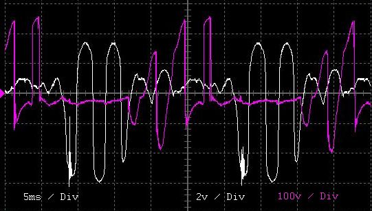
Pickup and Charge voltage at 2370RPM.
MEASUREMENTS
When measuring the CDI coil, don’t forget to reverse red and black probes of the multimeter for the same measure.
I may change the reading….
The ohms test on CDI side is not completely reliable. This only provides an indication but cannot replace a proper running test.
The ohms test on the STATOR side is much more reliable because it doesn’t contain any electronic components.
You will most likely never notice an intermittent failure…
LC4 kickstart Ignition coil with SEM TM14-04 TM14-07 before 1999 :
| Ohmmeter + pole | Ohmmeter – pole | Readings |
| CDI/Coil side: | ||
| red | black | 47k |
| red | green | 1Mohm to infinite/OL (or 47k?) |
| red | orange | 0ohm |
| black | ignition lead | 2,0Kohm (more or less 0.3K) |
| Stator side: | ||
| black | red | 1750 ohm |
| black | green | 23 ohm (+- 5 ohm) |
| red | green | 1750 ohm |
| yellow+yellow | blue | 0,2ohm |
LC4 kickstart Ignition coil with SEM TM14-05 after 1998 :
| Ohmmeter + pole | Ohmmeter – pole | Readings |
| CDI/Coil side: | ||
| red | black | 47k |
| red | green | 1Mohm to infinite/OL |
| red | orange | 0ohm |
| black | ignition lead | 2,0Kohm or 6.8kohm |
| Stator side (SEM K11): | ||
| black | red | 1750 ohm |
| black | green | 165 ohm (+- 20 ohm) |
| red | green | 1750 ohm |
| yellow | yellow | 1ohm |
KOKUSAN 2K-2 (replace SEM ignition after 1997) :
| Ohmmeter + pole | Ohmmeter – pole | Readings |
| Stator side: | ||
| red/black | red/white | 24 ohm (15%) Exciter |
| red | green | 100 ohm (15%) Pulser coil |
| ground | yellow | 0.7ohm |
KOKUSAN 2K-3:
| Ohmmeter + pole | Ohmmeter – pole | Readings |
| Stator side: | ||
| red/black | red/white | 13 ohm (15%) Exciter |
| red | green | 100 ohm (15%) Pulser coil |
| ground | yellow | 0.7ohm |
| white | yellow | 0.2ohm |
KOKUSAN 2K-4:
| Ohmmeter + pole | Ohmmeter – pole | Readings |
| Stator side: | ||
| red/black | red/white | 24 ohm (15%) Exciter |
| red | green | 100 ohm (15%) Pulser coil |
| yellow | yellow | 0.7ohm |
LC4 electric start with KOKUSAN
Impulse transmitter coil red green 100ohm more or less 20%
Stator black / red red / white 12,7ohm more or less 20%
loading coil mass / yellow 0,65ohm more or less 20%
loading coil white / yellow 0,16ohm more or less 20%
————————————————–
LC4 kickstart with KOKUSAN super comper 1999-2003
Impulse transmitter coil white green 60 -120ohm
stator red / black-yellow 0.45 – 0,56ohm
Stator black / red and red / black 0.45 – 0,56ohm
————————————————–
Ignition coil KOKUSAN
Primary blue / white – mass 0,45 – 0,56ohm
secondary blue / white – zundkabel 0.45 – 0,56ohm
————————————————-
TROUBLESHOOTING
Follow: https://transmic.fr/2021/10/07/ac-cdi-v27/#troubleshoot
REPLACEMENT
To replace a TM11-xx or TM14-xx ignition, you will need :
– an ACCDI v2.8+
– a box
– and a standalone capacitive ignition coil rated at least for 500cc.
(Suitable coils FOR CDI can be found on Ebay, Ebay, or Ignitech…)
How To wire an ACCDI v28+ to replace a TM1x-xx ACCDI with SEM stator.
How To wire an ACCDI v28+ to replace a TM1x-xx ACCDI with KOKUSAN stator.
To replace TM14-04/07 for 2 strokes with ACCDI v2.8+:
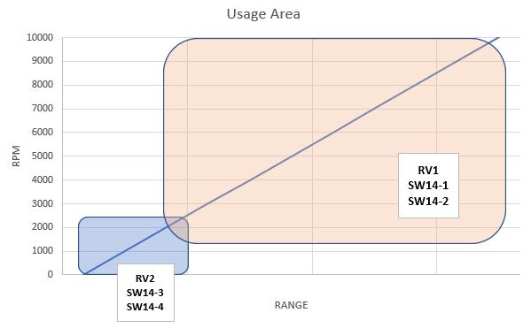
| SW13-1 ON | SW13-2 ON | SW13-3 OFF | SW13-4 OFF | SW13-5 ON | SW13-6 ON |
| SW14-1 ON/OFF | SW14-2 ON/OFF | SW14-3 OFF | SW14-4 OFF | SW14-5 ON | SW14-6 n/a |
| RV1: 0 to 1 |
| SW13-1 ON | SW13-2 ON | SW13-3 OFF | SW13-4 OFF | SW13-5 ON | SW13-6 ON |
| SW14-1 OFF | SW14-2 OFF | SW14-3 OFF | SW14-4 OFF | SW14-5 ON | SW14-6 n/a |
| RV1: 0 to 1 |
| SW13-1 ON | SW13-2 OFF | SW13-3 OFF | SW13-4 OFF | SW13-5 ON | SW13-6 ON |
| SW14-1 ON/OFF | SW14-2 ON/OFF | SW14-3 OFF | SW14-4 OFF | SW14-5 ON | SW14-6 n/a |
| RV1: n/a |
VIDEOS.
 KTM 360SX with ACCDIv28+
Thanks to Sam A. Thanks to William M.
I have a 87 LC4 580 KTM Require SEM Ignition Coil CAN YOU PLEASE HELP ME ! Mobile 0429491359
LOL
If you have a problem say it here, perhaps someone can help..
But there is no chance that I call you back 🙂
I’ve some available, cause mine GS620 SC stopped sparking instantly. You can also look for a replacement from Electrexworld but KTMdealers don’t love it. Steve from MOTOPLAT: http://www.uk-motoplat.com/ 0044 (0)7516 350 134 repairs them for a fixed price of 185 GBP
I’ve a KTM GS620 SC from 1996 with a kickstarter, it is a 4T . Who can give a suggestion or has already experience which CDI published on transmic.net is usable for this engine?
Hello found the schematic to be a little outdated any chance you can help source more modern components?
I am looking for an AC CDI for my KTM 620 (I think the ignition timing is either 36 or 38) will the AC CDI product you sell work for me?
Hello,
I would not say “outdated”, it’s not about Fashion !
This schematic is the genuine one from KTM using techno from the 2000’s
A processor is needed if you want to do fancy things but for triggering a SCR at 5 volts a diode do the job perfectly and in reliable manner.
Furthermore there is no battery on most of offroad KTM,Maico,Husky as µproc need a stable power…
AFAIK Your KTM620 can use a SEM ignition (AC-CDI) or Kokusan (DC-CDI)
Hi there, great page thanks for this info.
I have a 1996 KTM 620 with an SEM stator, getting no spark. After testing the resistance across the stator wires (all seem ok) i note that the black lead has continuity with the frame of the stator itself, and therefore the bike. Is that normal ?
i don’t understand how that could be given that the kill switch effectively connects the black lead of the coil (through the orange) to earth to kill the motor.
any ideas would be appreciated.
Hi, thanks!
Yes it’s normal, CDI is grounded to the frame through the black wire.
No, the orange wire kill the engine by connecting the RED wire to ground, (not the black one)
Disconnect the orange wire to check if you don’t have a permanent kill….
Th
ok cool sorry to be obtuse, but the cdi being grounded to the frame via the black means that the *stator being grounded to the frame via it’s ‘own’ metal body is normal. gonna try disconnecting the orange wire tonite.
cheers
Absolutely. cdi is grounded through the stator. Stator is connected to the frame.
ok i have a spark but it seems to my amateur eye that the spark is weak and / or intermittent. i am able to hold the sparking end of the plug against the frame and am only slightly uncomfortable with the shock, from memory it should give me a whack (i didn’t start by holding it in my fingers!). Up until now i have had intermittent probs including problems hot-starting, which i understand can point to a bad stator. Coil resistances are correct, plug lead and plug are ok. Gonna bite the bullet and replace the stator. I’ll let you know how it goes.
cheers
I incline to think it’s the CDI not the stator that it’s faulty.
do some measurements (voltmeter, oscillo) before spending some bucks!
Hi again, sorry to abuse your hospitality but you clearly know more about this than me.. I read your message below late and when ahead and ordered a stator. it arrived and i’ve installed it, in my opinion the spark is better and importantly consistent when the plug is outside of the bike. however, i have a serious ‘kickback’ problem, which i guess is caused by bad (too advanced?) timing. The new stator does not have a timing mark on it, and the old one didn’t either so i have no idea how to time it ! even on the most ‘retarded’ setting it kicks back (i cant go back any further), never used to do that with the old stator. is that further indication that the cdi is faulty? i don’t have an oscilloscope btw. i appreciate any advice you might have,.
It’s a SEM stator?
I think that the 3 bolts are not aligned so it’s not possible to fix it the wrong way… Right?
Have you at least compared your measurements on the CDI with the resistance map above ? Everything match?
Without any measurements neither oscilloscope traces done before and after replacement it’s just a shot in the dark !
sorry i should have been more explicit, i have measured the resistances of the cdi and they match your table above (SEM before 1999). You can potentially mount it 3 ways, by rotating it on the 3 holes, i have mounted it the way it appears in all the photos on the net (and the way i found the old one). after that there is a degree of movement to adjust the timing, because the holes are not circular. gonna get back out there tonite after finding some detailed pix on the net of the position of the marker, hoping its the same on mine. problem is this game is breaking my ankle !
The original SEM stator has a timing mark on the tight bump where is the pickup.
See: https://transmic.net/sem/stator.jpg
This line should be visible through the timing cover.
You must place the pickup coil of the new stator at the same place.
Hi again, sadly that’s not the case (i’m pretty sure), lookup in the pic on this page and you see that the inspection window is not correlated with the ‘poles’ of the stator, its kinda 5 o’clock if the pickup is noon. after playing in the garage there is only one way it can go, the way in your photo, and i’m not able to retard it enough for it to work… sigh.
Well we can assume it’s fit the good way then!
Seem you were right and the stator failed but the new one COULD be different and give too much voltage and the CDI trigger sooner…
Try to add a 1K adjustable resistor in series with the GREEN/pickup input wire.
I NEED A TM-14-04 IGNITION COILOR ANYONE THAT WOULD WORK ON MY 95. KTM 300 2 STROKE
Hi again, in my frustration i went ahead and bought a new cdi to go with the new stator.. ST5500L and CD5004. my thinking was that replacing the 2 together should eliminate any incompatibilities.. wrong. the kickback problem is still there. if i switch back to my old stator, the kickback problem goes away (with either cdi!), it can sometimes ‘just’ idle for ~10 s but then dies, the reason why i wanted to replace it in the first place. think i’m gonna try your idea of putting a 1k resistor on the pickup circuit to more closely emulate the original stator.
Use a 10k or 4k7 trimmer and adjust it…
hi again, i put an adjustable resister in series with the green pickup line. tried kicking it with the plug outside of the bike to see at what point the spark dies, for me i only needed to add about 30 ohms before it stopped sparking. wouldn’t start with the resister in place though. remove the resistor and it goes back to the kick-back behavior. i’m wondering if the company that supplied the stator mixed models, gonna ask them to send a replacement.
Instead of the trimmer, add 1 to 4 generic diodes, Cathode wired to the green cable on CDI side…
Thierry: YOU ARE THE MAN !!!!! I put 3 diodes in parallel with each other, in series between the cdi and stator and… VROOM ! no kickback, everything works ! would you mind explaining what this means ? please send me an email so i can send you a couple of beers :)))
Cool ! Thanks to consider buying me a beer! There is a Paypal Donate button on the left side of this page 😉
Definitely this adaptable stator is somewhat different…
follow-up on PM
hi what diodes exactly did you use for this and how do you wire them in parallel? my ktm 300 1999 has exactly the same problem where its sparking to soon and the kickback is almost breaking my foot. many thanks Luke
Hi, Not in parallel but INSERTED in SERIES with the pickup line!
2 or 3 general purpose diodes (1N4007) Cathode wired to the green cable on CDI side…
like here
Pingback: Diagnostika – ak sviečka nedáva iskru | Blog o motorkách
Hi
I have a KTM EXC 250 1998 with no spark.
I have checked SEM stator resistance values:
Black-Red- 1.7K Ohm
Black-Green- 168 Ohm
Green-Red- 1.9K Ohm (instead of 1.7K Ohm)
Yellow-Yellow-0.4 Ohm (instead of 1 Ohm)
Should I get a new stator or the values are OK?
Hi,
Those values are OK.
yellow / yellow is certainly 0,2ohm like models before ’99
Anyway yellow/yellow are the 12Vac coil and you don’t have issue with +12v Isn’t?
Long time, but I haven’t seen your reply and unfortunately the bike still doesn’t have a spark.
I never checked the 12V because the bike doesn’t have lights.
If the values are OK, should I order a CDI unit? Or the stator might still be the problem?
No I think the stator is fine. if you want confirmation, remove the sparkplug, rotate the crankshaft with a drill and measure the outcoming voltage.
ACCDI v26+ can do the job with an external standalone ign. coil
Thank you very much for your help.
How much voltage should I expect from charging coil and pickup coil ?
And another question- can I test the existing CDI using the 2 yellow wires and a 12-220 V transformer in order to replace the charging coil? Do I need to use a rectifier? If it can work, how exactly should I connect all parts?
IDK what YOUR multimeter will say!
Only True-RMS multimeters are able to accurately measure non-sinusoidal ac waveforms with irregular patterns, squares waves…
Look closely to the scope trace above: pkp: 2v/div , charging: 100v/division
https://transmic.fr/sem/2370rpmHT.jpg
You want to use the 12vac from the lights coils ?
Yes it should work more or less… Transformers are 50Hz and the AC signal is way more !
Or use 2 transformers: First a 220-12 connected on the 220vac main power, and a second 24-220 (in reverse mode)
So you should get 110Vac at the output.
Use a rectifier?
Only if you want to destroy your ACCDI 🙂
Yes, I want the lights coil to replace the charging coil.
Is it the correct way to connect ?:
Connect 1 yellow wire of the stator to each side of the 12v side of transformer.
Connect the 220v side of transformer to- bike frame, CDI red wire.
yes, as simple.
Hi Thierry,
I have a problem with sem tm 14-04 , all the measuremens are the same that sem 14-05?
The only difference i have found its coil green black , about 1.5Mohm (almost open)instead of 47Kohm
Is this ok for 14-04 or may i have to change for a new one?
Thanks in advance
Regards
Hi,
Yes except the pickup values are identical.
1.5Mohm is clearly out of spec measurement !! I think it’s faulty
Have someone to lend you one or build the ACCDI analog v2.4 is you know about electronic.
BR
thanks, Thierry
sorry I said wrong colour:
I said ignition coil green black , but really it´s ignition coil red green.( about 1.5Mohm (almost open)instead of 47Kohm),
therefore the ignition coil may be damaged.
Anyway my stator readings are ok, but the stator pickup it´s 165ohm
the bike it´s Aprilia Red Rose 125 1990 ,therefore , I assume that someone changed the stator for a new one ,
and leave the 14-04 ignition coil.
With this stator reading (165ohm) may I install 14-05 ?
or it will work with 14-04/14-07 ?
Regards
Hard to know…
I think it should work with TM14-04 but a 165ohm pickup provide more voltage and “could” harm a 14-04 sooner or latter…
Better is to go for a 14-05 to adapt stator and CDI
Thanks for your help Thierry, I will try to find a tm 14-05
Regards
Whats the trafo specs for the CDI ?? ( primary 100 turns 0.2mm2 & secondary 50 Turns 1mm2 ) or so
Honestly I don’t care when a new one for a 250cc cost only 10$…
🙂
Edit: The primary handle 200V and 10000V is the minimal value to get a spark at the secondary, so the ratio must be at least 1/50 until 1/100.
Wire are thinner then that: around 200turns of 0.8mm and 20000 x 0.05mm
HI Thierry is the stator 3 phase or single phase? There are 2 yellow wires and 1 light blue wire coming out of the stator for lighting. My bike is wired with the two yellow wired together then to the lighting and the blue to the chassis ground. My bike reads 12vac and the lighting has flickering at low RPM and the LED lights I added are very dim until I increase RPM. I have no Battery. Thanks for your continued support to this post
Hi,
My fault! it’s indeed 2yellow and 1blue (corrected above).
IMHO it’s a one phase. If you haven’t I suggest to replace the battery by a capacitor that will act as a current storage during the 80% of time when stator doesn’t give anything. (pulses of 15v during 20% of time)
This 47000uF/25v/18€ capacitor SHOULD fit…
If there was no battery and just AC, you MUST add a 5A bridge rectifier before the cap.
Thanks for the suggestion. The one I see in the parts fiche is 10,000 Mf, on the actual item is written 10,000uf. Which is confusing. Is it okay to oversize the capacitor in this situation?
what is confusing for me is the way you write it down!
I strongly doubt that a official datasheet says: 10,000 Mf with a comma and a capital M !!
LOL it’s simply the International Metric System 10mF = 10000uf
yes it’s OK.
Would these readings match for a 1995 400 LC4 with a left side ignition SEM K11/60 G-08?
I have no idea, I don’t think there were SEM K11/60 on 400LC4 in EU…
I bet there isn’t huge differences….
Hi Thierry, my compliments for all the explanation you are doing.
question: do you know anybody that installed any of your Ac-CDI in a Aprilia 650 (~BMW 650Funfuro). the old version earlier than 1995? The originals are difficult to get and old, so I am looking for a replacement. Apparently these old one worked with one trigger coil and one trigger from the generator..?
Hi,
Thanks. One person was interested to build one for Aprilia pegaso 650 GA 1994 (with one 240ohm pickup) but I don’t know if he followed up….
What is the reference of the box? I believe that
Nippon Denso 070000-0780 / 1992-1994 / 9wires are ACCDI
Nippon Denso 070000-0790 / 1995-1997? / 6 wires are DCCDI
Indeed, it is Nippon Densi 07000-2170 / 1992-94/ I think 9 wires and a 240 ohm pickup. And that is what puzzled me. Two different guys told me that the CDI has one external trigger and one of the AC coils is also a trigger. I have schematic of the stuff but am not sure how to compare these to yours.. your opinion is very much appreciated!
You can send me the schematic by PM. My email in on top right link “contact”
Is it a ACCDI too?
CDI can be triggered by external pickup or by the stator, but I never seen both at the same time! That is no reason to do so !
thierry, schematic is more connection setup to CDI and alternator not a schematic of the ignition (helas) you can find it here. Obviously it is a AC-CDI.
https://wetransfer.com/downloads/c4044dbb216301fab8b81cff37df835720191216170122/d0c06ecc03681676a6f7f2cdd409470f20191216170122/065fd6
A guy from carmo.nl told me the dual trigger story. It seems to be true as I still have a spark on the highest delay without using the separate trigger coil (and using another working CDI.)
all your idea are welcome.
It’s a wiring diagram not a schematic. it is here.
Well perhaps the external pickup has been added later on production to ease the kick start…?
Yamaha XT600 also had 2 pickup for low and high revs.
If and only if the internal pickup for hi revs puts out ONE pulse per rev, ACCDI v7.9 can be use. low(aka12°) attached to the external pkp, Hi(36°) to the internal one.
thanks, maybe I will do that and use only one pickup. With the successor of the bike >1995, they skipped the 2 for just 1 trigger (and used battery driven CDI). thanks for the input
Works with a single sensor! (I bought the PCb already in March for another project..:)). so, naturally I have to change the position of the magnet. (essentialy it is then the setup of the 1995+ Aprilia/BMW).
There is one other problem now. My impression is that the magnet is partly demagnitized or so. The signal is weak. did you ever encounter that, and what did you do? use another trigger coil (more windings, more ohms?)? or did you glue another magnet (seems a little tricky for underway..)
in any case thanks a lot for your help…
Great. I suppose you use the external pickup which is for LOW RPM, so you need to move it?
With some luck you can try the EXTRA-ADVANCE feature…
No I haven’t had. Beware ! Space between rotor tab and pickup is EXTREMELY sensitive. If the pickup is moved away from the tab for a tiny mm the signal gets weak.
A hall effect sensor is easy to glue, some guy here have done it. The MAJOR trick is to fit in very very tight, then with glue sealing it seem to carry on the heat well.
Hi Thierry, bought your PCB 7.9 (Printed Circuit Board AC-CDI 16F628 v7.9 ) in march last year. fiddled around with it quite much and finally build in a Pegaso (here above). now I d like to do that again, but V7.9 is not there anymore in the shop? do you still have one, or can I find PCB anywhere? Much obliged..,.
Petrus.
Have you ever worked on k10 with sem tm11-10 cdi? It’s 94 husky te350. Seems to have an additional wire for charge coil (red wire,blue wire), trying to figure out if I can wire this to a stator that has just red black green ignition wires. I have the stator unpotted. Good work on the Kim unit
No I haven’t seen a TM11-10.
If they kept the same color by function, then:
Black: GND Red: charging coil Orange: Kill sw Green: pickup
and there is only one extra wire: Blue.
I don’t know what it’s used for…. Any ohm measurement between blue and other wires?
I would probably connect the TM11-10 to the same colors on the stator and live the Blue wire disconnected.
It worked. Started right up. The blue wire is connected to the each charging coil between them on the outer edge with the red connected at the last one. My lights still don’t work. The whole reason for the stator swap. I get 5vdc at idle and with throttle it drops off
Cool!
Re the light what if you unplug the voltage regulator? if any…
one stator that should work: https://www.electrostator.com/fr/sm630/4117-stator-allumage-husqvarna-te350-te400-te410-tc500-tc510-te510-tx510-sm570r-sm570rr-tc570-te570-sm610r-tc610-te610-sm630r.html
man, can i reproduce the stator voltage from another source? like a car converter 12v-220vac
and use the pickup coil from the stator
i start an scooter with that method, but idk if its working on ktm lc4 540 sem ignition , tm 14 04
Yes it should. Power the CDI between Black(gnd) and Red wires
thanks and what cdi do you recomand for lc4 540 1998? from your site. i want to order one, i. am from romania
To replace a TM14-04: https://transmic.net/2020/05/12/ac-cdi-v25/
plus an external ignition coil rated for 500cc.
we have a problem with a replacement for the tm 14-05 i have a cd5004 from hpi (https://www.hpi.be/item.php?item=CD5004) and i have a problem with it and the same with my original tm 14-05. the problem is that i have infinte ohm between black and red , and between green and red do you maybe have an idea what the problem could be the replacement is new 1 time in use and have this issue could it be a problem with another part
MfG Tobias Hagen
Ps. Sry for my bad englisch i am not a native englisch speaker
Hi Thierry, bought your PCB 7.9 (Printed Circuit Board AC-CDI 16F628 v7.9 ) in march last year. fiddled around with it quite much and finally build in a Pegaso (here above). now I d like to do that again, but V7.9 is not there anymore in the shop? do you still have one, or can I find PCB anywhere? Much obliged..,.
Hi Thierry,
I have a KTM 300 95. It doesn’t spark.
I have checked SEM stator resistance values:
Black-Red- 1.7K Ohm
Black-Green- 162 Ohm
Green-Red- 1.9K Ohm
Yellow-Yellow-0.5 Ohm
I have checked the TM 14-07
Black-Red- 47K Ohm
Red-Orange- 0.3 Ohm
Green-Red- 300K Ohm
Black-Ignition Lead -Open Circuit
The coil appears to be broken. Can I install a TM14-06?
Thanks,
Ricardo
Hi Ricardo,
Yes I guess.
TM14-06 & TM14-07 have the same advance curve
TM14-04 has a different advance curve
TM14-04 TM14-06 TM14-07 share the same internal coil
Th
Hello,
I have ktm 250 1994 with SEM Ignition.
My flywheel magnet rotor broke. And there are no magnets left. Where i can find a new one ?
Hello! Could somebody please send a full description or all important details about the differences between TM14-xx variants?
I’m interested in the difference between the units. (Especially Tm14-01 and Tm14-04).
Thanks!
ktm 250 gs 1991 I have sem 14-07 damaged and I found 14-01 is it valid too?
I believe TM14-01 is limited to 7000rpm max and TM14-04, TM14-07 is 9500rpm
AND THAT MEANS? WHAT CAN I BE WORTH? Or it won’t go well
PERO FUNCIONA LA MOTO, ACEPTABLE?
Hi i have ktm lc4 that lost spark while running the cdi is bad. It poped and leaked out. It is tm11-08, i have measures stator and that seems ok. Can someone help me where to find it? Or what diferent part do buy ? Thanks
Is it the original CDI? I though TM11-08 was for 2stk and LC4 comes with TM14-05… Anyway there are not available anymore by KTM!
Read above how to adapt an ACCDIv26
Hello. I would like to replace my KTM coil TM14-07 with the ACCDI 2.6+unit. What size (voltage output or voltage multiplier) external coil I would need to pair it with to work correctly?
Thank in advance.
Hello,
Any ignition coil designed especially for CDI (never use those for TCI) and for the same CC that your bike.
There are more or less identical and unfortunately voltage ratio are never mentioned. It’s a shot in the dark!
The original one is 0.3ohm primary and secondary is: 5.8Kohm / around 40Henri
BR
The coil I plan to use is from a 2007 Kawasaki ninja 500 which I believe is a CDI system with 1 coil per cylinder (250cc each). The primary has 4 ohm resistance and the secondary has 19.9K ohm resistance. That’s a pretty big difference from the numbers you cited above. Is there a chance of damage on my new ACCDI 2.6?
>4 ohm resistance and the secondary has 19.9K ohm resistance ?? OMG !
To my understanding it seems to be a TCI coil, not a CDI coil. There are not equivalent at all!
it “can” damage the CDI and if it doesn’t, performances will be poor.
one correction. The readings are 4 ohm for the primary and 14.5K ohm for the secondary. I originally measured through the spark plug cap with a 5k ohm resistance. I do believe the bike it comes from, 2007 ninja 500, is a CDI bike. I did start it up and it does work. But I will not continue to use it if you believe it could damage the CDI in the ling run.
BTW, I love the ACCDI 2.6. Great job!
After further research, I stand corrected. It does appear to be a TCI coil. I will find something different.
Thanks.
Sure. Better stop to use it !
I am replacing the TM14-07 CDI on a 95 KTM 250exc. I have 2 questions.
1. I purchased the ACCDI 2.6 but the capacitor is a L105J 400V P0118, (not the one shown in the 2.6 image L105J 250V E0920). Will this work on a 95 ktm 250exc 2 stroke? Do I need the 2.6+ instead?
2. I can see that I should cut open the JP3 jumper to lower the timing advance for the 2 stroke. Do I still need to change the potentiometer to modify what happens at high RPM or is that only for 4 stroke setups?
I look forward to your response.
Thank you,,
Steve
1) No worries. “L105J 400V” is stronger than “L105J 250V” no need to upgrade to 2.6+
2) No JP3 is not for 2strokes. JP3 cut is used to set the timing for KTM.
but JP4 is to be close for 2stk use.
Potentiometer is always used. Start with max position 4 then decrease slowly while trying to rev up the engine. When it wants to rev up you’ve got the setup.
Yes I misspoke on JP3. I did cut it.
I will close JP4 as suggested
And thank you for the additional info on the potentiometer.
Again, the ACCDI 2.6 is a great product! it brought my old KTM back to life!
I own a ’94 620 SX(kickstart only) and i am not sure but i believe the stator has gone bad.At first i thought it was the regulator because my lights kept burning(all of a sudden lights would go really bright and burn). Regulator is the old single phase(OEM 491.11.434.000). I tried the replacement regulator (OEM 58311034200) but i get same issue – lights will get really bright and burn. Spark seems to have no issue. I am not sure though which are the correct resistance values for this stator? Also, the cdi i cannot tell which part number it has(i think it is TM 14-05).
What readings should i get from stator? Should i just buy a new stator, either from Electrex or from RM Stator?
Thanks a lot for any info/advice you can give me.
Hi,
It’s certainly a TM14-05 and for the stator readings, I don’t hide anything, ALL values that I know are on the page and in the comments.
how much AC before the reg at idle and high revs.?
how much DC after the reg at idle and high revs.?
I would check in the order:
1) a bad fuse (no battery load = regulator cannot work)
2) a bad battery or bad connection to battery (no battery load = regulator cannot work)
3) a bad ground (bad gnd = regulator cannot work) Check wires, cnx to frame and stator cnx
4) a faulty stator.
Compare oscilloscope AC traces with the ones on my page.
Th
Hi and thanks for fast reply! Really appreciate it.
The bike has no battery-straight kickstart only 🙂
I will have to check the readings again but when it burned the lights the regulator showed more than 23-25v – in last measurement it reached 42v!!
I will have to check again with the regulator, but previous readings where around 13v at idle and then sudden spike and it goes over 20v and it burns the lights.
Regarding the oHM readings you have above: You have ohm readings for stator with 14-05 cdi after 1998 or before 1999 with 14-04
So, if my cdi is probably 14-05 i should get these values stator side:
black red 1,7kohm
black green 165 ohm more or less 20 ohm
red green 1,7kohm
yellow yellow 1ohm
I will check again the ground as you said. Which wirse cnx to frame you mean?
42v sometimes! That’s brings down to:
3) a bad ground: regulator is connected to the frame=gnd
Check all eye connectors screwed on the frame, every black or brown wires (check wiring diagram for colors)
5) bad connection between regulator and main load/light (no load = regulator can’t work)
Re the stator, those readings are for the ignition part of it. As the spark is great and ignition coil is separate from light coil, reading are not relevant. Only light coil readings are useful to know and they are around 0.2, 0.3 volts (until 1ohm) between gnd and yellow.
Hi Thierry, I’m hoping you might be able to shed some light on this no spark issue I got going on here. I read through a ton of your posts above but didn’t quite see a 2000 KTM 400 SXC… It seems impossible to find ignition coil info. I got the bike used, the crank bearing seized so I split the cases and rebuilt the motor. Bike sat for a year or two and now has no spark. So I got new gas, plugs, battery. Had the carb serviced by a local shop (keihin FCR, i think 38) and actually put a new stator just a few days ago to no avail. So it has to be the coil right? So of course its 20 years old and they don’t make them anymore. But there has to be a way to wire up the red, green, and black wires from the new stator to an aftermarket coil right? The two yellows and the yellow/blue goes to the voltage regulator. It seems someone took out the original capacitor and put in a 12v battery. the kill switch is ok, there is no on/off switch, no kick stand or clutch switch. Oh and its kick start only 🙂 Any advise would be greatly appreciated.
– JP
Hi Jacques,
Sure there aren’t much info on KTM ignition over the internet… Neither at the dealer.
Ah the crank bearing seized. Those engine don’t like to be driven at low rpm, there are way too much vibrations. Risk is less with a driver who always ride WOT !
The stator having been changed to no avail, no kill sw, the fault tend to be on the ignition box…
When you said an aftermarket coil I’m unsure you’re aware that it’s not a ign. coil but a CDI plus an ignition coil both glued in one single box!
You’ve to find a second hand TM14-05 box or to adapt an aftermarket CDI plus an external coil.
See https://transmic.fr/wp-content/sem/cablageACCDIv26KTM.pdf for the wiring.
Th
Hello sir,
I have a 93 ktm mxc bought used with no manual. I’m not getting spark. How do I set my volt meter to check the coil for resistance? There are 4 wires, green, orange (kill switch), Red & Black. I removed the coil and I’m not sure of the readings and what ohm settings to test the wires on.
Hello,
Haven’t you read the page above?
Ohm readings are written at “Flywheel and stator” for exciter side
plus “ignition coil” paragraph for CDI side.
Hello Thierry,
my bike is a lc4 350 year 1994 4-stroke kickstarter only without battery or capacitor.
sometimes it struggles to start and, after so many kicks, once it has turned on, keeping the gear at a certain number of rpm, it seems to be sobbing, jolting such as it has an electrical problem (but i feel that it could go more).
In trying to understand what the problem was, I realized that, while a TM14-05 SEM ignition – 101 890 00 should be mounted by the manual, my bike has a TM14-04 SEM ignition – 101 888 00 (tipically used for 2 strokes bike????).
Verifying the TM14-04 with a multimeter I have the following values:
red – black = 47 kilo ohm ok
red – green = 6.2 Mega ohm instead of 47 kilo ohm !!!!!!!
red – orange = 0 ohm ok
black – spark cable = 2.16 ohm ok
Could it be the cause of the above symptoms? (considered: a) the model different from the stock one b) the wrong value between the red and the green wire)
Could I solve it with an AC-CDI v2.7 combined with the “standalone capacitive ignition coil rated at least for 500cc”?
I also measured the stator with the multimeter on resistance (which in my opinion has also been changed as it no longer has the gray cover marked sem) as per the ktm manual and my values are as follows:
black – red = 1.33 kohm instead of 1.7kohm
red – black = 1.3 kohm instead of 1.7kohm
black – green = 25.7 ohm instead of 23 ohm ± 5 ohm
green – black = 25.7 ohms instead of 23 ohms ± 5 ohms
red – green = 1.33 kohm instead of 1.7kohm
green – red = 1.33 kohm instead of 1.7kohm
Do you think these values are tolerable? or should the stator be changed too?
thank you in advance
p.s. How much are the shipping costs for Italy? in how many days would I receive everything?
Hi,
TM14-04 are for 2 strokes so you will get poor perf and piston overheat at high revs! But I bet no problem at kick start.
Stators values are quite in the 20% range so I think it’s OK but TM14-04 values are out of specs.
You can find a new TM14-05 or this AC-CDI v2.7 plus an extra ign. coil.
>How much are the shipping costs for Italy? in how many days ?
It depends on the shipping method you choose! Add it in your cart to view the cost then cancel the order.
Thank you very much, you are very kind
Do you think a tm 11-08 (for 4 strokes) would be good? could i cause damage elsewhere in trying it to determine if cdi is the cause of all my troubles?
best regardz
TM 11 – 03 switch 01 ON delay ignition or not? Now I have set 4 fixed times advance as per SEM scheme. But I was wondering if SW 14 switch 1 ON could work. Thanks
>Now I have set 4 fixed times advance as per SEM scheme.
I don’t understand.
Once again PLEASE READ the setting for TM11-03 above.
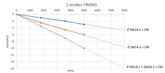
TM11-03 is for 2 strokes so there are 3 possibilities TO TEST ON YOUR BIKE :
SW14-1 ON and SW14-2 OFF
SW14-1 OFF and SW14-2 ON
SW14-1 ON and SW14-2 ON
TM 11 03 is fixed advance so I followed what the diagram says.I try to set it for 2 times then. Now I have mounted the blue coil tm14-04 and it works because it is backwards compatible with the black TM11-03. I’ll let you know how it goes with the sw14 switches activated. Thanks
Hey Thierry (or others!),
I have sucessfully installed your great ACCDI 2.7 instead of a SEM TM14-04 on my RS125 with ROTAX123.
I chose https://www.ebay.de/itm/352138645292?hash=item51fd194f2c:g:kjUAAOSw2FZho2dz as an ignition coil – was that the right choice? (I changed the spark plug boot for my original/correct NGK one)
Now I (surely) want maximum performance!
How do I test wich combination of SW14-1/-2 is the optimal ignition curve?
How do I correctly set -RV1? I know it needs to be between 0 and 1 but ist there a tutorial on how to get it optimal?
Sorry for probably not understanding what you have already written xD
Thank you!
Hi, Great!
The ignition coil is OK. It fits ATV 400cc that use a DC-CDI and fit 660cc so it’s strong !
Perhaps unnecessarily strong for a 125cc…
>How do I test wich combination of SW14-1/-2 is the optimal ignition curve?
Probably : SW14-1 + SW14-2 or only SW14-2
If you really serious about it, you need to test on a power bench and select which one gives the more power.
If you just use your “ass” to measure, then select the one that gives the best acceleration.
Use a phone App to measure acceleration (ie : DIABLO™ SUPER BIKER)
Also try to climb a hill at high revs.
For RV1 settings? Same thing: A power bench !
Otherwise :
– Run the bike at idle with RV1 at max value (4)
– Try to rev up the engine while slowly unscrew (toward 0) until the bikes wants to rev up.
– When she wants to rev up you’ve got the setup.
Ride the bike and adjust a bit according to your feeling…
Do you confirm the settings: SW13:1,2,5,6=on SW14:1,2,5=on ??
Hi, Thierry
I have an aprillia rx 125 (tm 14-04) and i ordered an accdi 2.6 in the past. It was fine with jp3 cut open and jp4 soldered and it was starting easily, i accidentaly shorted the pcb and it’s got fried. Ordered a second one and used the same settings as before, but its kicking back now with the same settings. Tried messing with dip switches and rv and its doesen’t helped as i expected. Should i cut jp2 to lower the advance even more? I don’t really understand why it’s not working ,because it was working fine with only jp3 cut before.
Thank you in advance.
Hi Roland,
You’ve connected it exactly as before?
First thing first give me a complete information:
What are the version printed on the back of the 2 PCB?
What is the setup? (ALL sw and jumpers)?
Th
Both of them are ACCDI V2R6C5. The setting that i used on the firs one: Jp3 cut open, Jp4 soldered togerther, dip 1 off, 2 on, 3 off, 4 on ,5 off , 6 off. This is an older settigs from this website and it was starting up first kick, but with the second accdi2.6 it was kicking back every 15-20 kicks with the same settings , if rv is on min then i get kickbacks, but if it’s on max then i don’t get any , but it won’t start. I tried the current dip settings on this website ( dip 1 ON 2 ON 3 OFF 4 OFF 5 ON 6 ON and 1 ON 2 ON 3 OFF 4 ON 5 OFF 6 OFF) it was not starting and kicking back with both settings.
Stator green cable connected to high, black connected to gnd, red to alt on the pcb.
Then it’s the same production batch,I don’t understand too, there are no difference in components!
The safer setting for TM14-04 is 2,4:ON / 1,3,5,6: Off / JP3 open/ JP4 close
Keep this setting above and cut JP2 too.
If it doesn’t work: close again JP2 and add a 12ohm resistor between HI input and Ground.
Now tried using 2,4:ON / 1,3,5,6: Off / JP3 open/ JP4 close/JP2 open and it’s kicking back harder, im going to try to mess with the settings more, if I don’t succed then i will try soldering a resistor between hi and ground. Thank you very much for helping!
Hi again, i tested my working ACCDI V2R6C5(i had spark, but at wrong time) with a multimeter. I set the multimeter on the led tester/ beaping setting or whatever is it called. if i put one end of the multimeter on the HI and the other end at D7 led (p side ) on the pcb, i get a really really weak blue light from the D8 led . On my other ACCDI V2R6C5, if i do the same thing with that one , i get a really bright light, but that cdi is not working and i found out that R4 have no resistance on that one. Which one worth reparing?
Hi,
So happy that I ran into this website, since there seems to be a lot of helpful information over here.
So my ignition seems to work well, but the old owner of the bike made a mess of the wiring harness and as well the voltage regulator(s) are not working. My bike is a LC4 of 1995 (model without battery), so the entire circuit for lighting is AC right now. Because I will have to buy a new voltage regulator anyway, I was planning to change the entire circuit to DC by buying a voltage-regulator with integrated rectifier (so I can connect for example a USB-charger in the future). If I understood correctly from the workshop-books that came with my motorcycle, my ignition is a SEM 130W K11/60G-08 which is a single-phase stator. I found a schematic of how a single phase generator can be used with a 4-pin voltage regulator in order to get 12V/DC on this page (3rd diagram/schematic): https://www.homemade-circuits.com/understanding-motorcycle-voltage/
I was hoping that this would work for my ignition too, but I am not sure if my single phase ´spool´ also has two ends in order to connect it like this and if it has I am also not sure which two wires to use. There are three wires coming from the stator for the lighting circuit which are yellow, yellow and blue. First of all I thought that maybe I have to wire the two AC input pins of the 4-pin voltage regulator between the two yellow wires coming from the stator, but now I am in a doubt.. Can I mess things up if I connect it wrong? I am quite unsure about it right now, and was hoping that you or anyone else might has more experience with this (I am quite new into all this, but find it really interesting).
Thanks in advance!
Hi,
For KTM400-600 LC4 1995, the wiring of the SEM 130W K11/60G-08 single-phase stator is:
yellow + yellow connected together (according to the diagram) = 1 wire
Blue = second wire
Both are connected to the 2 AC input pins of the regulator. (Like 3rd diagram right)
Don’t take my words for it, check out how much ohm you read between blue and yellow (should be 0.3-1ohm), yellow and yellow
>I was hoping that this would work for my ignition too,
The ignition has nothing to do with the lighting coil it’s totally separate.
>Can I mess things up if I connect it wrong?
It depends how much you mess up 🙂 Generally stator handles shorts if it lasts a few seconds at idle…
I have been working for some time on trying to start my 1987 KTM 600 lc 4. I replaced both the stator and CDI/coil with a HPI system and I have spark. However, no attempt to start. Have gone through other potential causes many times. However, the one thing that I suspect but cannot check is if the CDI is commanding the coil to fire at the wrong time. I know this would be a long shot but I am running out items to check. How could I have the CDI tested to verify it is asking for the correct timing?
Which HPI system do you have? ST5500L + CD5004?
If there is spark, it can be the timing that’s out.
if possible move a bit the stator to trigger sooner or latter.
Only a timing lamp can show you when the spark appends, refer to https://transmic.fr/2021/09/23/read-timing-from-flywheel/
but if the engine doesn’t start you’ll have just 2 or 3 sparks that would make the reading difficult if not impossible…
Hi Thierry.
Thanks for your response and sorry for my late response. I was abroad for the last 2 weeks, but luckiliy I have been able to do some testing this weekend.
So I ordered a 4-pin regulator/rectifier (type: SH721AA) and connected the two ´phase pins´ with the yellow/yellow and the blue wire coming from the stator. I was then hoping to measure 12V/DC between the black and red wire coming from the 4-pin voltage regulator/rectifier but I measured only 6V/DC instead?
I also measured the resistance as you told, between the blue and yellow and yellow and yellow (all where between 0.3-1ohm, so I assume thats OK then).
Then I also measured the AC voltage coming from the stator (measured between blue and yellow/yellow) and that gave between 12-30V/AC (depending on the RPM of the engine). So I assume that´s also OK.
So I am not sure why I only get 6V/DC after the regulator/rectifier I bought. The manual that came with the regulator/rectifier (SH721AA) said it was supposed to be connected like this:
– White wire = Stator phase (I connected the blue wire from the stator to this one)
– Yellow wire = Stator phase (I connected the two other yellow/yellow wires from the stator to this one)
– Black wire = GND
– Red wire = 12V/DC
I didn´t connect the black and red wire to the frame and/or wiring harness of my KTM. Only measured between these two wires, and that gave 6V/DC. Could this be a faulty regulator/rectifier or could it be that it doesn´t match my stator?
Hello! I have 1995 Ktm lc4 620
The problem with the bike is that I can’t get it to start. There is compression (new piston), spark and new fuel. I have checked timing and valve clearance also the stator seems to be in good condition and it has been measured. Sometimes the bike backfires to the carburettor but that’s all. Bike has only kickstarter.
Bike hasn’t run in about seven years. When I last rode it it started to smoke and it ran poorly. Now i got the inspiration and decided to get it running again and I replaced the piston, gaskets and rebuilt the carb. (dellorto) but it still won’t start
The coil TM 14-05 101 890 00 had 3 Kohm in the black wire when it should have 2,0Kohm (more or less 0.3K) could this be the reason why the bike won’t start?
Hi, it could be sparkplug wire or sparkplug.
or the CDI+coil TM14-05 can give a spark outside the engine but no or weak spark inside the cylinder. (weak coil)
or a faulty TM14-05 unit on witch timing went wrong (once the backfire).
Thanks for the quick response. The sparkplug is new so maybe I’ll replace the coil and see if that helps.
1) the ACCDI v2.7 appliance of your production can mount on the APRILIA AF1 PROJECT 108 CC 125 motorcycle in replacement of the coil
SEM-
TM11 0310140700
(Insert photos of your reel)
2) If, as per pattern, need coil
https://transmic.fr/wp-content/ACCDIv25/cablagePCBv27tac.pdf
3) Given that come from your connection pattern
https://transmic.fr/wp-content/ACCDIv25/cablagePCBv27tac.pdf
ACCDI v2.7 card needs COIL PICUP
Unfortunately the APRILIA AF1 project 108 cc 125 motorcycle is not equipped with PICUP COIL but with electronic RAVE control unit
So what’s connected to her place?
4) possible connection pattern in replacement of the old SEM coil-
TM11 0310140700
I don’t understand everything you wrote….
If the bike uses a TM11-03 like this one: https://www.ebay.it/itm/144319062966 190€ used !!!!
Than ACCDIv27 can replace TM11-03 with an new external coil. (coil was inside TM11-03)
Wiring is described in THIS page, same wiring as TM14-xx. just read it.
Hi, i finaly figured out my problem with my cdi… I have written about my problem a few months ago. I actually got a faulty ACCDIV2R6C5. The dip switch 3 is not working properly. it’s not working when i switch it on, it’s only works when the switch is stuck at the 3/4 of the way. Coused me so much headache. Could that cause ignition timing issue?
Hi, Well done. So this Red DIP switch is defective?
Perhaps you can spray KF Kontakt on the switch and flip it a couple of time to clean the contact or just weld a short between pins.
Yes that causes a timing issue !
ACCDIv27 is using different DIP switches.
Hi, firstly can I say great site and thanks for sharing the masses of knowledge and information,
I’m helping a friend with a badly running 1993 KTM 300 exc he’s just been robbed with, after all the usual checks I now believe it to have a faulty SEM ignition causing its main problem,
The problem is it will start first time every time and idle perfectly but makes little power and will not rev out past (by ear) mid revs , I’ve read other posts that have described exactly the same problem and fixed it by changing to the Kokusan ignition however that’s too expensive to do right now so we have ordered an ACCDI v2.7 and standalone coil to replace the existing TM 14-07 unit. I did see the previous owner had Im sure quite wrongly connected the kill switch so it grounded the green pickup line of the coil making my amateur brain wonder if that had not destroyed but damaged the cdi causing no advance as the rpm’s built..?
I could still use some advice and clarification on my readings though especially with regards to the stator side before I connect the new ACCDI to it.
TM14-07 CDI / Coil side readings…….. Red to Black = 47k ohms Red to Green = OL Red to Orange = 0ohms and black to plug lead can be anything from the correct 2kohms to infinite depending how much inward pressure applied to the lead.. always infinite with lead removed and no pressure on the screw.
SEM (K11 I think) stator readings…. Black to Red = 780ohms Black to Green = 150ohms Red to Green = 1380ohms Lights not in use but show 0.6ohms.. I was hoping to see 1.7k rather than 780 and 1380 but I also read that the meter used to measure can affect those two readings and 500 to 2k ohms can be expected..?
Sorry for the long post just wanted to include all relevant info,
Any help thoughts or advice greatly appreciated thanks….
Hi Gary,
Thanks for this novel, I’ll read it this WE 🙂
To begin with I don’t think that the kill wire shorting the pickup to ground can damage the CDI.
But the stator readings are questioning me more…
Is it the original SEM stator or an aftermarket one?
pickup Black to Green = 150ohms seems quite OK
Charging coil Black to Red = 780ohms is extremely low…
With a diode involved have you considered reversing the ohmmeter probes for this measure? yes? some reading ?
>always infinite with lead removed and no pressure on the screw.
Since the reading depend on the pressure inward the plug wire, I think it’s oxidized or the 5k internal resistance is broken…
My first guess is that the engine bog on at mid-range because of not enough spark energy (bad secondary coil or/and bad charging coil on stator)
my2cent
Hi Thierry,
Thanks for getting back to me and well done for staying awake all the way to the end… (assuming you did lol)
As yet I havn’t had a chance to pull the flywheel and stator so cant say for sure at present OEM or Aftermarket,
Ive checked the charging coil resistance again as you suggested with the polarity reversed and yes its now showing a healthier 1260ohms if that’s a good thing.. the manual agrees with your diagram above and says to measure the first way but if your happy I wont harm the new ACCDI with it I’m very happy.. I do have access to a later Kokusan stator and flywheel but its owner wants access to my 300 euros so if possible It would be good to prove the existing stator faulty first..
Not too important as its going in the bin but with regards the cdi/coil again briefly, the diagram above for that model 14-07 says 47k expected from red to green but this ones infinite, I cant help wondering what if anything that signifies.?
Thanks again for taking the time to read and reply to these your 2cent is very much appreciated..
Glad to help.
I should consider dealing Kokusan ignition instead of weed ! 🙂
Re the TM14-07 that says 47k between Red (charging input) and Green (pickup) for the life of me I can’t remember where I got this or what year it is for…
Considering how SEM CDIs were built it’s far more logical to have no connectivity between them. So I just modified the diagram above.
LMK how it goes.
Lol… Yes definitely mate you’ll know how its gone from the beer in your inbox the first time I get a reading of 10k via tacho rather than multimeter 8o)
When your free would you try the tracking for me.. I’m like a kid a week before christmas but I don’t think La Poste likes me very much or possibly I’m not using the right tracking number.. Thanks again…
https://www.laposte.fr/outils/track-a-parcel?code=CW065523307FR
Hello, I have installed v2. 7 on an aprilia rs 125 and I have a problem, the bike doesn’t stretch, it’s hard to turn up, I’ve placed the pins as in the table, I’d like to know if there’s any more adjustment to the potentiometer or something in particular
Hi, You don’t give me much information!
Which ignition was it in the first place? TM11-?? TM14-??
>I’ve placed the pins as in the table
which table? which setting exactly?
Hello, it is a tm14-04 I have sw13:1 2 5 6 on/3 4 off and in sw14:1 2 5 on/3 4 off and RV1 between 0 and 1
What I saw from the photos is that the board you sent me is the one with two potentiometers, RV1 and RV2, which would be the v27+ and I had ordered the v27, I don’t know if it will work equally well for the aprilia rs 125
Yes v27+ will work on Aprilia RS125
Test all combinations of SW14-1 SW14-2 being on or off. Test different position of RV1 and RV2
Below is where switches and potentiometers are acting:
Hello, I have tried all the configurations of the sw 14 1 and 2 and the potentiometers but when I go high rpm when cutting and giving gas again it falters and it takes time to pick up rpm again
When I come out of a stop, the rpm goes up quite well, but the problem is when I am driving when I cut gas, it does not recover, it makes a vacuum until it recovers rpm again.
Hello,
I don’t know. In the original SEM cdi the timing is the same when hot or cold. ACCDIv27 is the same as SEM: no timing difference hot or cold.
You changed the timing with SW14-1,2 and potentiometers and the problem is the same, so perhaps it’s no related to timing !
Hello, I have a query, the high coil that I have put on it for a rs 125 for the v27+ is from a mito of 125 would that be worth it or would it have to be from a motorcycle with more displacement?
A coil from a Mito125 for a Aprilia 125 is OK. You don’t need to have a “bigger” ignition coil.
Well, I’ve tried the four possibilities of sw14 1 and 2 and the potentiometers and I can’t get the bike to work, with an original tm14-04 that they left me the bike works perfectly, I don’t know if another different configuration can be tried
Yes you can try other configurations for TM14-04.
for exemple you can try:
SW13 1 and 2 on. 3 and 4 off. 5 and 6 on.
SW14 1 and 2 off. 3, 4 and 5 on.
Hello, I have tried the last configuration that you sent me and it still does not work, with the one that works best is with SW13 1,2,5,6 on and 3.4 off and SW14 1,2,5 on and 3.4 off but It still doesn’t work, I don’t know what else I can see
>but It still doesn’t work
By “doesn’t work” you mean the bike runs fine but the engine hesitate when you cut the throttle and wide open it again?
The only thing that is useful is to take the SAME scope snapshot with TM14-04 and with ACCDIv27 (at same RPM) to compare the timing.
EXACTLY like: https://transmic.fr/wp-content/sem/2880rpm.jpg
Or use a timing lamp with TM14-04 and with ACCDIv27 to compare timing.
It’s the ONLY useful piece of information. I cannot guess otherwise…!
I own a 1993 KTM 600 LC4, she didn’t have spark, so I bought the AC-CDI v2.7.
I configured the dip switches as mentioned in the KTM section:
SW13-1 ON SW13-2 ON SW13-3 OFF SW13-4 OFF SW13-5 ON SW13-6 ON
SW14-1 OFF SW14-2 OFF SW14-3 OFF SW14-4 OFF SW14-5 ON SW14-6 n/a
RV1: 0 to 1
I didn’t try RV1 = 1 and RV2 is in the middle position(2).
Now she has spark (and fuel) but doesn’t start.
Is painful to kick-start the engine, do you have prior experience with this engine generation?
Thank you
Pedro
(Post moved in the good section.)
Was it a TM14-05 ?
>I didn’t try RV1 = 1 and RV2 is in the middle position(2).
Why ??? There are 2 adjustable potentionmeters. It’s on purpose !
You can also try: SW14-3 ON SW14-4 ON
Será que habrá otro cdi que se le podrá adaptar a la husqvarna te 410 año 96??
Hello Thierry!
I wanted to ask you if you have any experience with the aftermarket stators for LC4 pre 99(OEM #58031002050).
The ones i find available are from HPI,Electrex,RMstator etc. But they seem awfully alike with the ones from China founbd on ebay.
The ones on HPI , electrex and RMstator cost around 200+ euros and ive read in some forums from people who bought them that they were hit and miss – just like the chinese ones..So, it could as well be they are just re-selling the chinese ones for a higher price.
Have you had any experience with any of those stators?
Hi,
Sorry I have zero experience with aftermarket stators. I never ever bought one.
I would probably let it rewound…
Hello i got to wire my ktm 300egs with kokusan 2k-2 i tried as the scheme described it but still no spark any suggestions. The motor was originally with sem but i replaced stator and flywheel with kokusan and i still dont have spark need help
Follow “Troubleshooting” procedure on https://transmic.fr/2023/12/16/ac-cdi-v28/
Good morning,
I bought a 1989 ktm er 600 lc4 without a battery and it doesn’t spark the spark plug. The stator was a bit rusty and measuring with a tester the values are as follows:
black-green 24 ohm
black-red 1660 ohm
green-red 1686 ohm
yellow (2 joined together) -blue 0.8 ohm
The CDI coil Sem TM 11-08 101855500 has the following values:
orange-red 1.2 ohm
red-black 1450 Kohm
red-green 880 Kohm, green-red 1500 Kohm
black-green 153 ohm
green-plug exit 2200 ohm
red-plug exit infinite
plug cable 3 ohm
plug pipette 55 Kohm
Where should I investigate in your opinion?
Thanks, Moreno
Hi,
I think that what you call “plug pipette” is the spark plug cap.
Spark plug caps have no resistor or 1k or 5k or 10k internal resistor, mostly 5k but not 55 Kohm IMHO
Grazie per la risposta,
l’ultima misura non era 55 Kohm ma 5,5. Scusa
Ho visto che è la cgi/bobina che non funziona e ho acquistato il tuo ANALOG AC-CDI v2.8+ con relativa scatola.
Vorrei aggiungere una piccola batteria (1,3 ah) per avere le luci ok a bassi giri. Devo mantenere il raddrizzatore/regolator e e collegarla a valle dello stesso. Giusto?
Non avendo chiave nè blocca manubrio con chiave né frecce, potrei collegare il safety 1 al deviatore frecce se è alimentato a 12 V, Giusto?