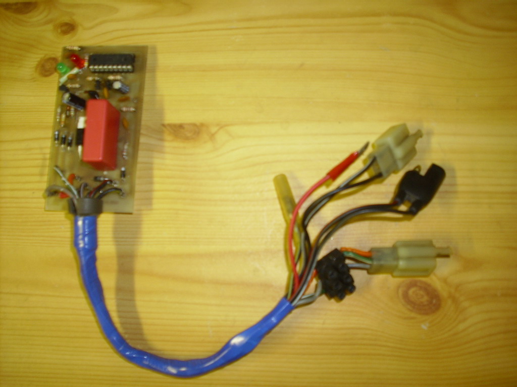
This AC-CDI is End Of Live
[ARCHIVE] An adaptation from 
Features
- Based on : PIC16f628 v6.5
- for singlecylinder.
- 1 advance curve programmed.
- No RPM limitation.
Introduction.
This adaptation was design for a DR600 SJ model 1988 that use a CDI with 2 sensors, this adaptation does NOT work on previous models fitted only one single sensor.
The functioning is quite similar to the XT 600, just reverse two wires..
Be aware that the DR600 pickup signal is different and requires some modifications on the circuit and into the software.
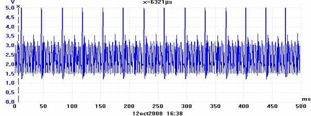
The 0 degree pickup ( called “no-kickback”) generates a lot of electric noise at high speed, which is not possible to reduce subsequently reduce because the signal must be stronger enough at kick start. If we reduce the signal, the noise disappear but the signal will be too weak at very low rpm (kick start).
So it is necessary to leave it for kick-start, then to disable it above a certain RPM.
Here is the pickup signal at 1600 rpm:
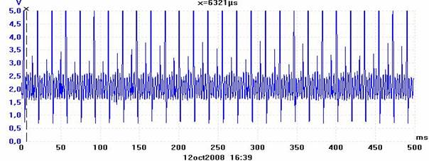
The 30 degrees sensor, also generates noise at high speed, just decrease the voltage in order to only keep the main shape.
Here is the pickup signal at 3500 rpm:
Therefore, to use the transmic CDI, we will have to make some modifications to the circuit.
Software.
Here is the .HEX for DR600 to burn into the PIC with this timing curve.
| Source HEX |
Advance curve | |
| PIC16f628 for Suzuki DR600 |
DR600.ZIP | 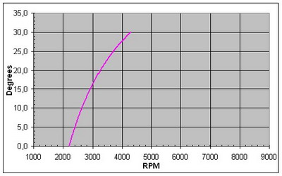 |
From 0 to 2200rpm, the CDI is using the 0 degree pickup.
Over 2200 rpm, the CDI is using the 30 degrees pickup, and applies a delay that gradually decreases until it reaches 4300 rpm.
Schematic.
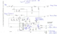
Here is the modifications made on the XT600 schematic:
PCB.
The circuitry hasn’t been redesigned for the DR600, so you’ll have to tweak a bit to add the new components.
Use the schematic above, check out the transistor datasheet.
Components.
Replaced parts
T1 = BT151
C11 = 1uf
R7 = 220 instead of 360 = 0 deg pickup Filter
R8 = 330k instead of 560 = 30 deg pickup Filter
Added parts
| R99 = 27 R98 = 4k6 D99 = Led T99 = Transistor BC547 |
 |
Leds
There are 3 LEDs on the PCB that have different meaning:
| D1 D99 D2 |
= White = Green = Red |
= Power on = Low RPM (pickup 0deg ) = High RPM (pickup 30deg ) |
Housing
The box size is 100 x 65 x 33 (Item 11009 in Gotronic)
Drill some holes for wires and to see the LEDs
It stands at the same place, you can secure it with a clamp and foam:
Connections.
Connect the stand and the neutral contacts
CDI shutdown when stand is deployed is not managed by the CDI. So you don’t have to connect it to the CDI, connect it to the blue wire to keep the neutral lamp working.
Connection to the power
This new CDI need +12Vdc battery to power the PIC
Take the +12v at the blinking relay.
Changing the common ground of the pickups
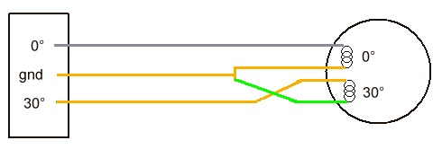
- Originaly, wires from the two pickups are separated. (2 wires for one pickups, 2 wires for the other, with separate ground)
- Under the tank, both pickup’s grounds are connected together and to a Orange wire that goes to the cdi.
- At the Suzuki CDI, there are 3 wires (commun ground= orange, pickup 0deg= gray, pickup 30deg = green)

For this DIY CDI, you have to reverse the connection of the pickup 30deg only.
So you have to separate the Orange wire under the tank and connect it directly to the 30° input of the CDI.
Connect the green wire to the commun ground.
Doing that, the signal will be positive than negative as expected by the CDI, instead of being neg/pos as it is with the genuine CDI.
Getting Started.
Once finish the tests on Transmic’s page, plug the CDI into the bike.
- First of all, unscrew the spark plug and connect it the a good metal part.
- Connect to the +12v: white LED is turning on.
- Kick Start : the green LED is flashing and sparks appear, using the 1st pickup at 0deg.
- Swith off the CDI, screw the spark plug in and start the bike.
- The green Led is flashing at iddle.
- Revs a bit and you’ll see the Red Led flashing meaning that the cdi is using the 2nd pickup at 30deg.

